You can run the Benwake CE30-A with the same 7.4v battery pack that you would use to drive the car. (It says it wants 12v but it works fine with less than that).
If you want to create a shorter cable. the connectors used by the CAN-to-USB converter board are JST-GH 1.25mm 4-pin connectors. You can buy them here.
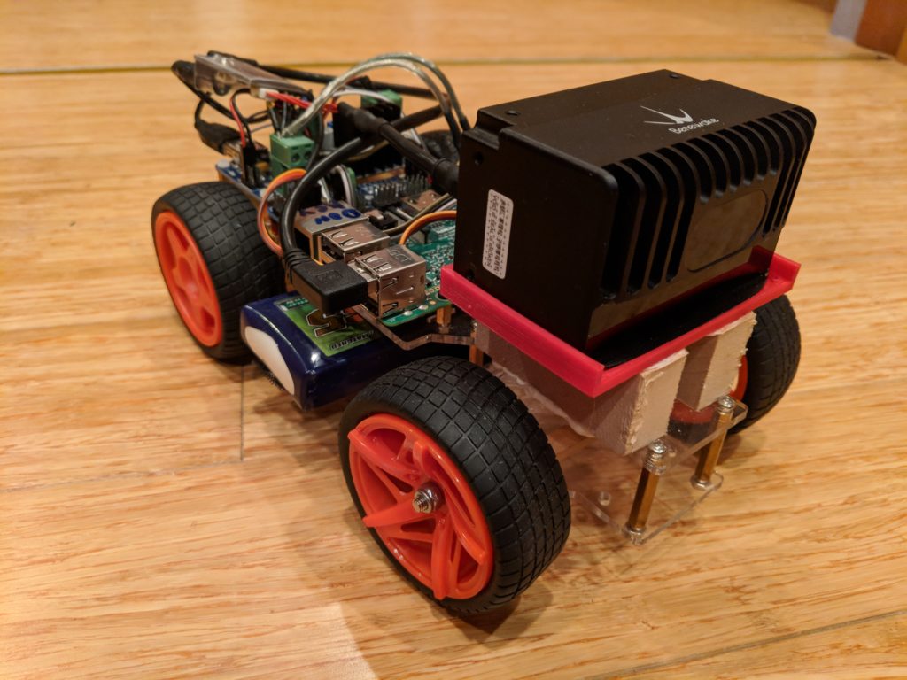
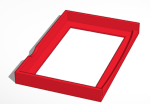
You can 3D print a mount for the LIDAR. I’ve posted a 3D-printable file here. Just raise it above the steering servo with some blocks of wood as shown here:
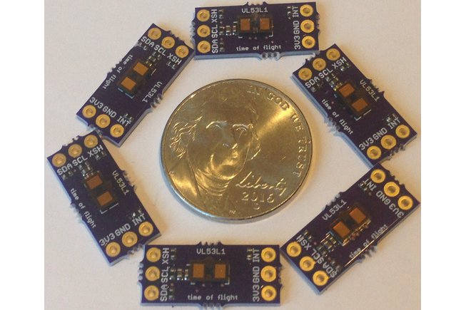
A year after announcing it, ST has finally released the new version of its tiny laser time-of-flight distance sensor with twice the range of the previous version. Called the VL53L1 (the previous version was the VL53L0), it’s available in chip form for $5 and in a breakout board from Tindie for $19 or a nicer one with connectors and mounting holes from Sparkfun for $25. These are chips originally designed for proximity sensors for smartphones (that’s how the phones can tell if you’re holding them up to your ear and dim/turn off the screen), and are very reliable. The claimed range is up to 4m indoors (up from 2m with the previous version), and since it’s a laser it has a very narrow beam (unlike sonar) and is appropriate for obstacle detection in DIY Robocars.
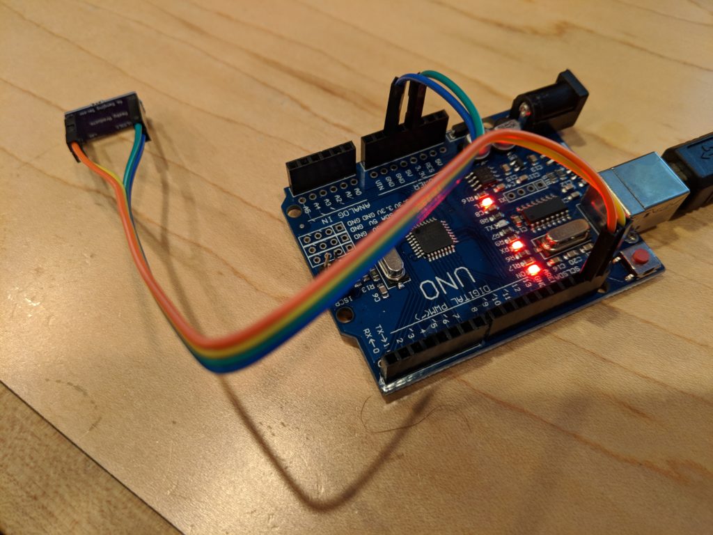
Sparkfun has just release an Arduino library for it, and the example code works well with both the Sparkfun and Tindie versions. If you want to try it, just connect either breakout boards SCL and SDA pins to the Arduino SCL and SDA pins and the voltage to the Arduino’s 3.3v pin and GND, as shown here:
In my testing so far, I’m only getting reliable reading up to 2.3m (7.5 feet), but there are some special high-power settings that you can enable, although they are not yet supported in the Sparkfun library. That said, that’s more than enough for 1/10th scale robocars indoors, and is far more accurate than the broad-beam sonar or IR sensors that would otherwise be used for low-cost obstacle detection.
Outdoors, it’s pretty much useless, especially in bright sunlight. Expect no more than 1m outdoors even in the shade, so I’d recommend a different sensor such as sonar or a somewhat more expensive 1D lidar like the TFMini ($40) for that.
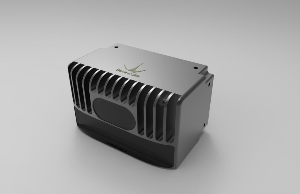
The era of small, cheap (sub-$1,000) Lidar is upon us, but it’s still a bit in its teething stage. In this post, I’ll give some initial hands-on impressions of one of the first solid-state 3D (actually closer to 2.5D) Lidars to hit the market, the Benewake CE30 series, which has just been released.
Unlike the other Lidars I’ve been using, such as the RP-Lidar A2/A3 series and (now discontinued) Scanse Sweep, which are rotating 2D Lidars (just viewing a thin horizontal disc around themselves), the CE30 has no moving parts and has both horizontal and (limited) vertical scanning (132° horizontal and 9° vertical), as well as an impressive 4m-30m range (depending on which version you get) as well as an excellent 20Hz refresh rate. That’s perfect for small autonomous cars like ours — solid state means nothing to break in a crash, and having a vertical as well a horizontal sweep means that we can see obstacles from ground level to above the car.
Initial testing confirms the 4m range, dropping to about 3.5m in bright sunlight outdoors, which is quite good.
Official pricing ranges from less than $1,000 to $1,500, depending on the version, but at volume they’ll be available for $400-$500. If you want to buy one now in single units, you can find them on Roboshop: the CE30-A (USB version) is currently $999, the CE30-C (ethernet version) is $1,195 and the CE30-D (long range) is $1,499.
Here’s a table that shows how they compare:
CE30-A
CE30-C
CE30-D
Max range
4m
4m
30m
Interface
USB/CAN
Ethernet
Ethernet
Notes
Only obstacle detection
Point cloud, no built-in obstacle detection
Point cloud. 4mm larger in width and height
Typical single-unit price
$800
$1,000
$1,500
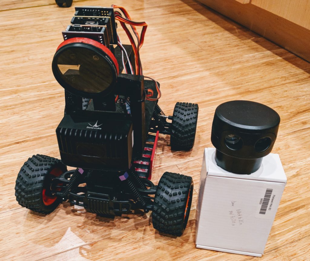
Size-wise, it’s about the same size as the 2D Lidars, which is to say just right for our cars. (It’s shown above mounted on a Donkeycar, next to a Scanse Sweep for comparison).
I’ve posted a mount for it here, which you can 3D print for your car:
Here’s a screen-capture of the sort of data it provides (me in my workshop waving my arms like a dork). The top window is the uncorrected depth map and the bottom window is a top-down view.
The software support is still pretty minimalistic: a Windows demo program (shown above) and C++ libraries for Windows and Linux (including ROS). The Linux library is designed for x86 computers and won’t compile on a RaspberryPi (which is ARM-based) yet, but Benewake says that compatibility is coming soon. Stay tuned while I wait for that — I’m particularly interested in the built-in obstacle detection mode of the CE30-A, but want to run it on the RPi.
[Update: CE30-C Python code that runs on RaspberryPi is here. CE30-A Python code is here]
One of the tricky things if you’re using the CE30-C (ethernet interface) with a RaspberryPi is figuring out how to talk to the Lidar on Ethernet at the same time you’re connected to the Internet (or another network) over Wifi. After a lot of research and asking around, I finally figured it out. Raspian (the RaspberryPi Linux distro) has been changing its networking configuration process with each version, which makes it hard to find reliable tutorials online, but for the latest version (Raspian Stretch), edit your etc/dhcpcd.conf file to include these two lines:
This will assign your Ethernet port to the CE30, while leaving your Wifi adapter free to connect to your regular Wifi network.
Needless to say, if you opt for the USB version (CE30-A) you don’t need to deal with this — it just shows up as a serial port.
Finally, here’s Benewake’s promotional video that shows what these Lidar’s are really designed for.
Next post will be after I get the software up and running in an autonomous car stack. But so far so good!
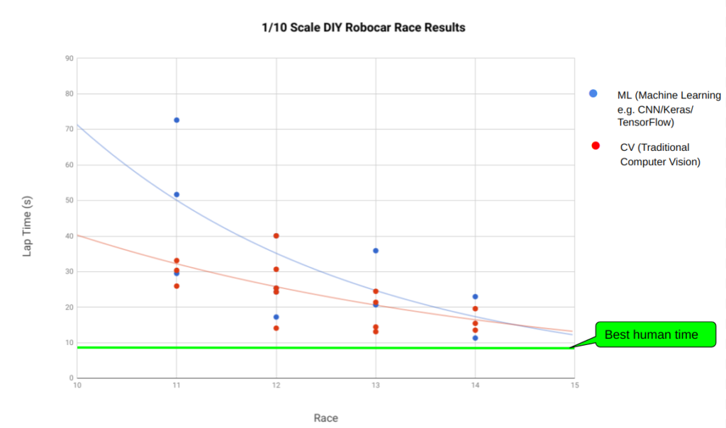
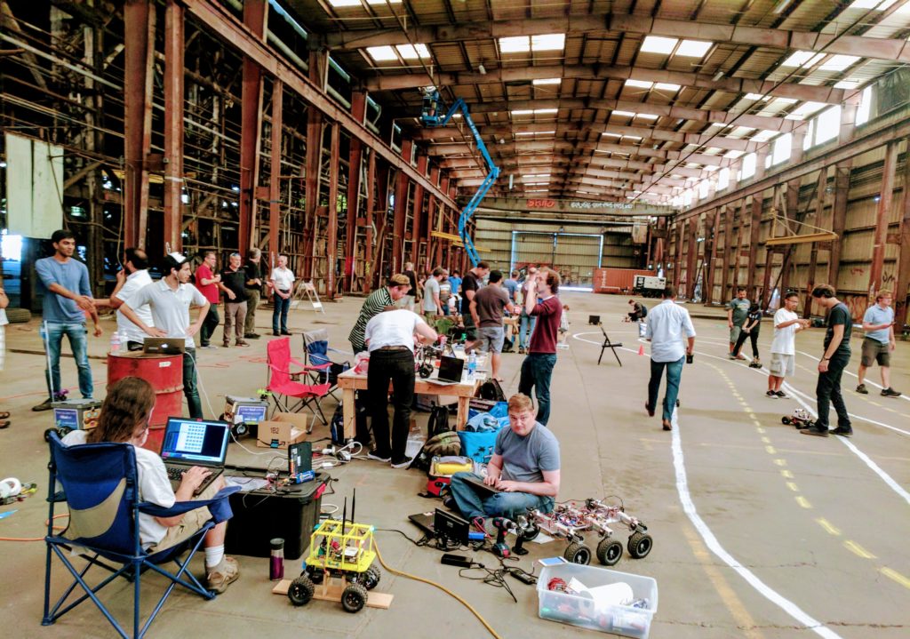
The semi-monthly Oakland DIY Robocars races have now moved next door to the American Steel Poplar Gallery, which has a shiny, slippery polished concrete floor, so we’ve recalculated the performance metrics just to compare races on that track (as opposed to the rougher track at Pacific Pipe next door). The data from the past four races are above (just the top five in each race), and you can see some clear trends:
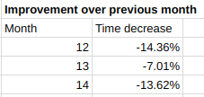
1) An average race-to-race improvement of top finisher of about 10%:
2) Less of a gap between the top 5 cars, suggesting that people are starting to dial things in better
3) A machine learning car (Carputer) is currently in first place, but the next three are computer vision (most of them using OpenMV). That suggests that ML is potentially better, but harder to get working well, which agrees with our real-world experience.
4) At this pace, the autonomous cars will beat the best human time in the next 2-4 months. It’s worth noting we don’t actually know what the “best human time” is for this track because we don’t know any humans who can drive RC cars particularly well, so this is a guess based on the best driving we can do. Since the ML cars use “behavioral cloning” (the human drives while the car records the data, then the car attempts to do the same at 1.3-1.5x speed), the ML cars that use this technique are by definition faster than their masters. But that doesn’t mean that they could beat any human.
5) The really fun part is the “all cars demolition derby” at the end. Pay particular attention to the tiny car on the outside, which is a Minimum Viable Racer built by Eric. He was a good sport about following the Fight Club rules (“If this is your first night, you must race”) and we promised him we’d help him rebuild it if it got crushed. The race isn’t over until Eric is done!
It’s been almost exactly a year since we started the DIY Robocars communities, and the growth has been incredible. Here, in numbers, is what we’ve accomplished over the year.
More than 20 race/hack events at our Oakland base. More than 2,000 total attendees.
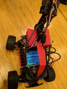
One of the problems of using RaspberryPi-based cars with Wifi connection is that even if you set them to auto-connect to a certain Wifi access point, you never know what their IP address will be, so you have to waste time search for them on the network. A good way to get around that (and to also display car information without having to SSH in via a terminal) is to mount a screen on the RaspberryPi, as shown above. I like the Adafruit 3.5″ TFT screen, which fits nicely on top of the Pi.
However, it’s not obvious how to get the screen to show your IP address once you connect, especially since the Wifi takes longer to connect than the Pi does to boot up, so any programs that run at bootup won’t be able to get the IP. I searched for a while and then finally gave up and wrote it from scratch. Here’s what you need to do:
First, edit the “crontab” file, which automatically runs programs at launch or at any frequency. At the the command prompt, type “crontab -e”, which will ask you to select an editor. Select Nano, and add this line at the bottom of the file:
@reboot sleep 10; sudo python ip.py > /dev/tty1
Let me explain what that line does:
The “@reboot” part says to do this once after every reboot.
The “sleep 10;” part says to delay for ten seconds to give the Wifi time to connect.
The “sudo python ip.py” part says to run a Python script called ip.py, which we’ll add next
The “> /dev/tty1” part says to send the text output to the screen, which is called tty1.
Now we have to create the “ip.py” file that will display the IP address. Type “sudo nano ip.py” to create the file and paste this:
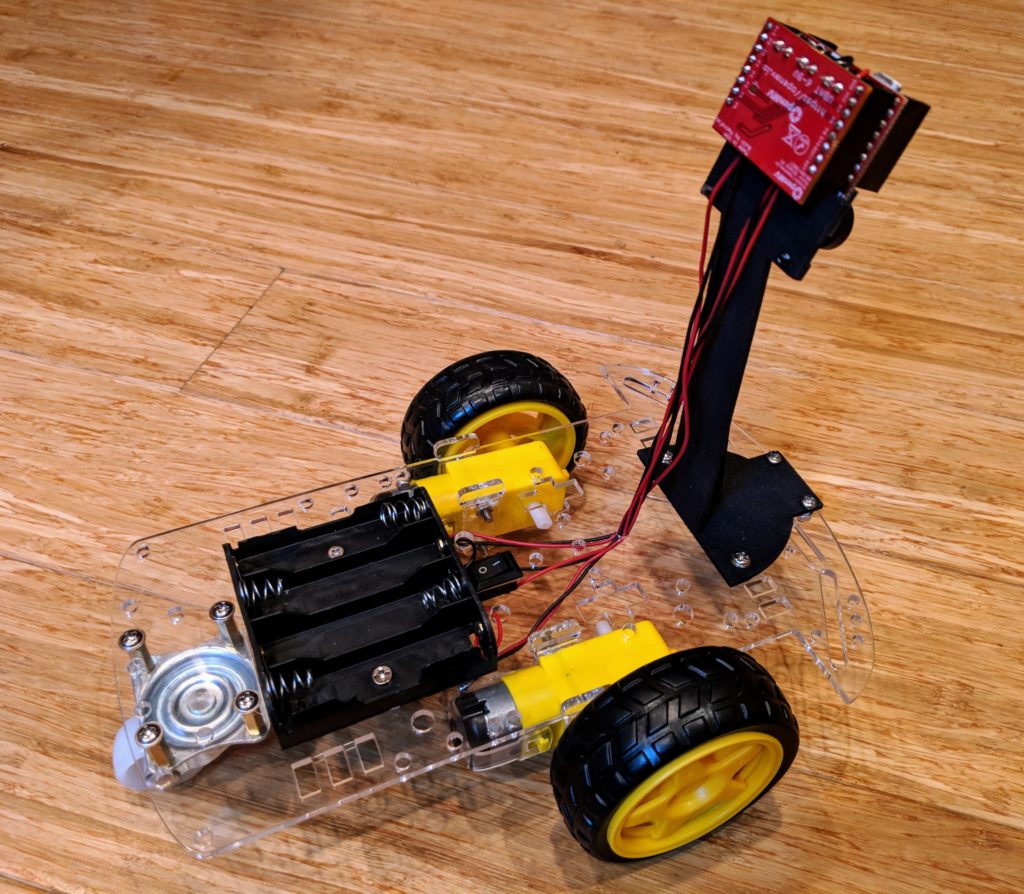
This is the cheapest good computer vision autonomous car you can make — less than $90! It uses the fantastic OpenMV camera, with its easy-to-use software and IDE, as well as a low-cost chassis that is fast enough for student use. It can follow lanes of any color, objects, faces and even other cars. It’s as close to a self-driving Tesla as you’re going to get for less than $100 😉
It’s perfect for student competitions, where a number of cars can be built and raced against each other in an afternoon. NEW BONUS: If you want to move to a more advanced linear-regression code, instructions are here
3D Printed OpenMV mount ($12 from Shapeways. Free if you have your own 3D printer). If you want to modify it, the original files are on TinkerCad here.
(If you don’t already have this): Some 22-gauge wire to extend the motor and battery wires to the camera ($6).
Also, a cheaper motor driver board ($7) can be substituted if you don’t mind a slightly less neat installation. For instructions on using that, see this note.
Total: $85 to $120, depending on which options you choose and whether you can 3D print your own parts.
1) Cut two 12″ lengths of black and red wire pairs, and strip 1/4″ from each end. These will be the wires to connect your motors to the OpenMV board.
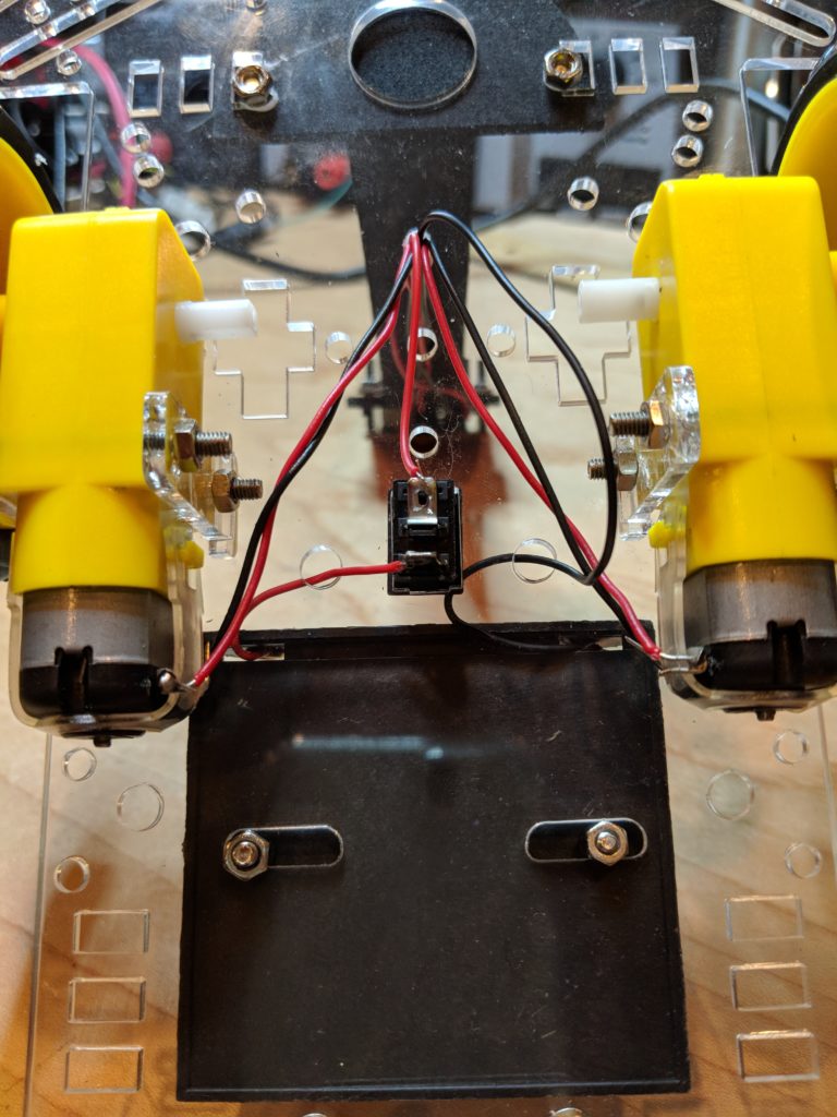
2) Assemble the rover kit as per the instructions, soldering the wire you just cut to the motor terminals (for consistency, solder the red wires to the terminals furthest from the chassis and the black wires to the terminals closest to the chassis, as shown in the picture below). We can always switch them at the motor driver side later, but this will make it easier not to get confused). Don’t overtighten the motor mounts; they’re fragile. If you break one, you can 3D print a replacement with this file, buy them from Shapeways here, or just cut it out of 3.5mm plywood.
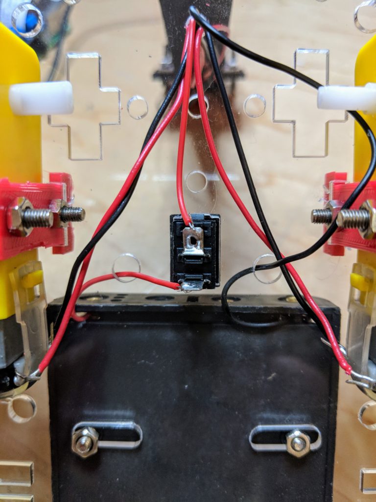
3) As for the rocker on/off switch, just snap it into place on the chassis, then snip the red battery wire an inch from the battery case and solder that to one of the switch’s terminals, then solder the rest of the wire to the other terminal as shown here:
4) 3D print (or have printed at Shapeways) the camera mount. Attach it to the chassis with screws as shown in the pictures above.
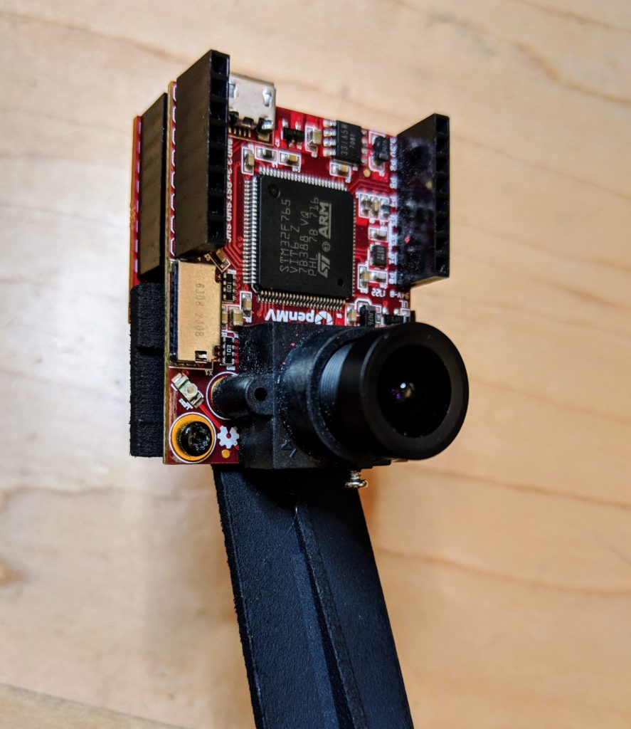
5) Screw the OpenMV camera to the mount as shown:
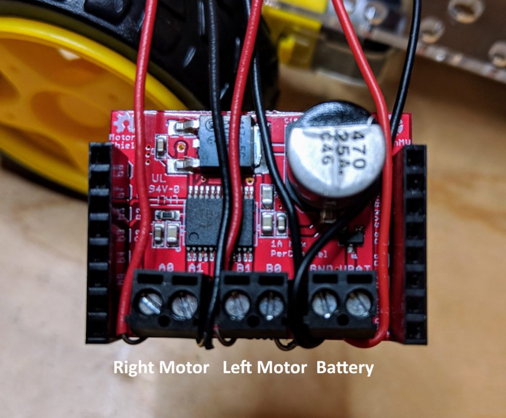
6) Attach the motor and battery wires to the OpenMV motor shield as shown below. Once you’re done, carefully insert it into the connectors at the back of the OpenMV cam.
7) Load the code into the OpenMV IDE, plug your USB cable into the OpenMV board and run it while it’s looking at a green object (it defaults to following green, although that’s easy to change to any other color in the IDE). (Make sure your rover is powered on with batteries in). If one of the motors is turning backwards, just swap the wires from that motor going into the motor controller.
Here’s how to test it and ensure it’s working:
8) If the rover tends to turn one way or the other, you can correct the “center” position by modifying the value in this line:
steering_center = 30 # set to your car servo's center point
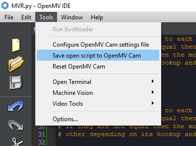
9) Once you’re happy with the way the code is working, you can load it so it will start automatically even if a USB cable is not connected by selecting “Save open script to OpenMV Cam” in the Tools menu, as shown:
Code tweaking tips
If you want it to follow a different color, just change this number in the code:
threshold_index = 1
# 0 for red, 1 for green, 2 for blue
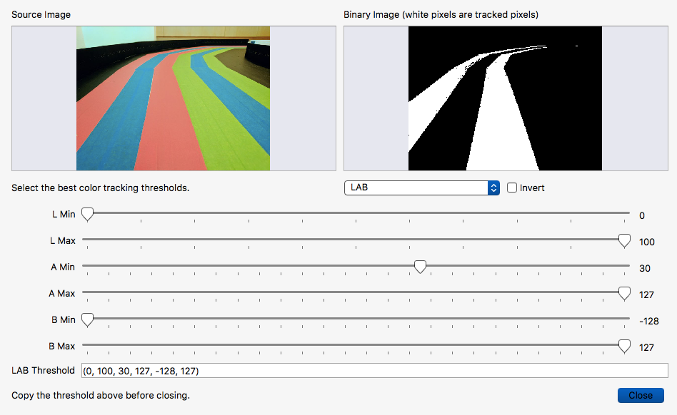
If you want to tune it for another color, or adjust it so it follows the color you’ve selected better for the specific tape and lighting you’ve got, use the IDE’s built-in Threshold Editor (Tools/Machines/Vision/Threshold Editor) and add a threshold set for the color (or replace one of the generic thresholds) that you want in this section of the code:
thresholds = [(0, 100, -1, 127, -25, 127), # generic_red_thresholds
              (0, 100, -87, 18, -128, 33), # generic_green_thresholds
              (0, 100, -128, -10, -128, 51)] # generic_blue_thresholds
# You may pass up to 16 thresholds above. However, it's not really possible to segment any
# scene with 16 thresholds before color thresholds start to overlap heavily.
In the below example, I’ve tuned it to look for red lanes. So I’d copy the “(0,100,30,127,-128,127)” and replace the generic red threshold numbers above with that. Then I’d change the line above that to “threshold_index = 0”, so it would look for the first threshold in the list, which is red (lists are “zero-based”, so they start at zero).
When you’re done, the IDE will show it tracking a color lane like the above (the lowest rectangular “region of interest” — ROI — is weighted highest, with the other two weighted less). You can modify the ROIs by dragging boxes on the screen to show the region you want to identify, and then give it a weighting as show here:
# Each ROI is (x, y, w, h). The line detection algorithm will try to find the
# centroid of the largest blob in each ROI. The x position of the centroids
# will then be averaged with different weights where the most weight is assigned
# to the ROI near the bottom of the image and less to the next ROI and so on.
ROIS = [ # [ROI, weight]
(38,1,90,38, 0.4),
(35,40,109,43,0.2),
(0,79,160,41,0.6)
]
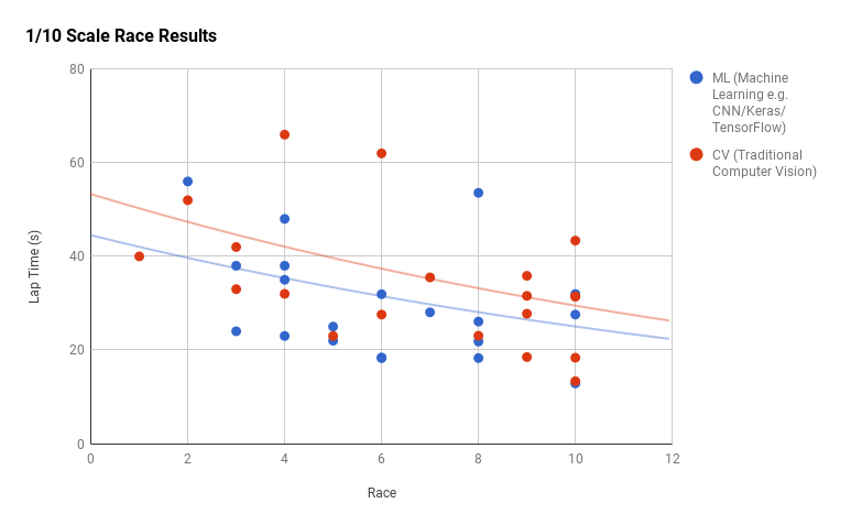
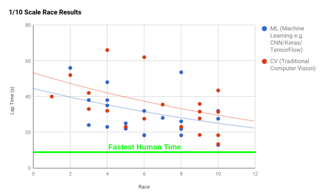
Here’s the latest data from the DIY Robocar monthly race series, thanks to our Track Master, Adam Conway.
A few things to note about these results:
The gap between traditional computer vision techniques (“CV”) and convolutional neural network machine learning (“ML”, also known as AI/deep learning/CNN) is shrinking.
The best of both will probably beat the best human drivers by the end of the year
This is in some sense a proxy war for the philosophical debate between the two approaches that is playing out in the full-sized self-driving car industry. Google/Waymo represents the ML-centric approach, while Tesla represents the CV-centric approach.
In both CV and ML, the top teams are using custom code. The two standard platforms — Donkey for ML and OpenMV for CV — are not yet beating the custom rigs. But over time, with more adoptions and collective development, there’s no reason why they can’t.
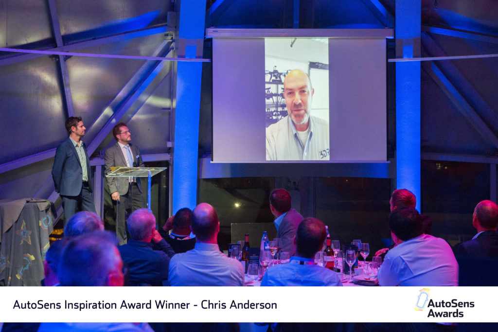
I’m thrilled that this community won the AutoSens Inspiration Award at the AutoWorld Conference in Brussels this week!
We’ve got nearly 1,070 members in our Meetup Group, and the monthly races in Oakland are getting bigger each time. Meanwhile there are another 500 members of the growing number of regional DIY Robocars groups around the world.
Want to set up a DIY Robocars race/hack event in your own town, like the folks in DC, Austin, NYC and elsewhere have? Go for it — it’s easy!
All you need is a room that’s big enough (the standard track is about 30m x 20m, although you can use any size you want that will fit in your room) and some tape (or paint if you want to make it permanent).
Free free to use the DIY Robocars branding on your own Meetup page. The graphics are here. Just use what you want and please link back to the mothership on your own site
Want to use a RGB track? Here are instructions on how to make that.
Comment here and we’ll add you to the master list of local meetup groups around the world.
A few tips:
Train in the morning, break for pizza lunch, race at 1:00
In the invite, suggest that people with cars come in the morning to get ready, and spectators come for/after lunch for the races. It’s boring watching people train!
Saturdays are best
If you have or can borrow a PA system, that will help with the race announcing
Try to keep it fun, low pressure and welcoming to people of all skills. Today’s casual spectator can be tomorrow’s competitor if you spark their imagination!