First impressions of the new Zumi robot car
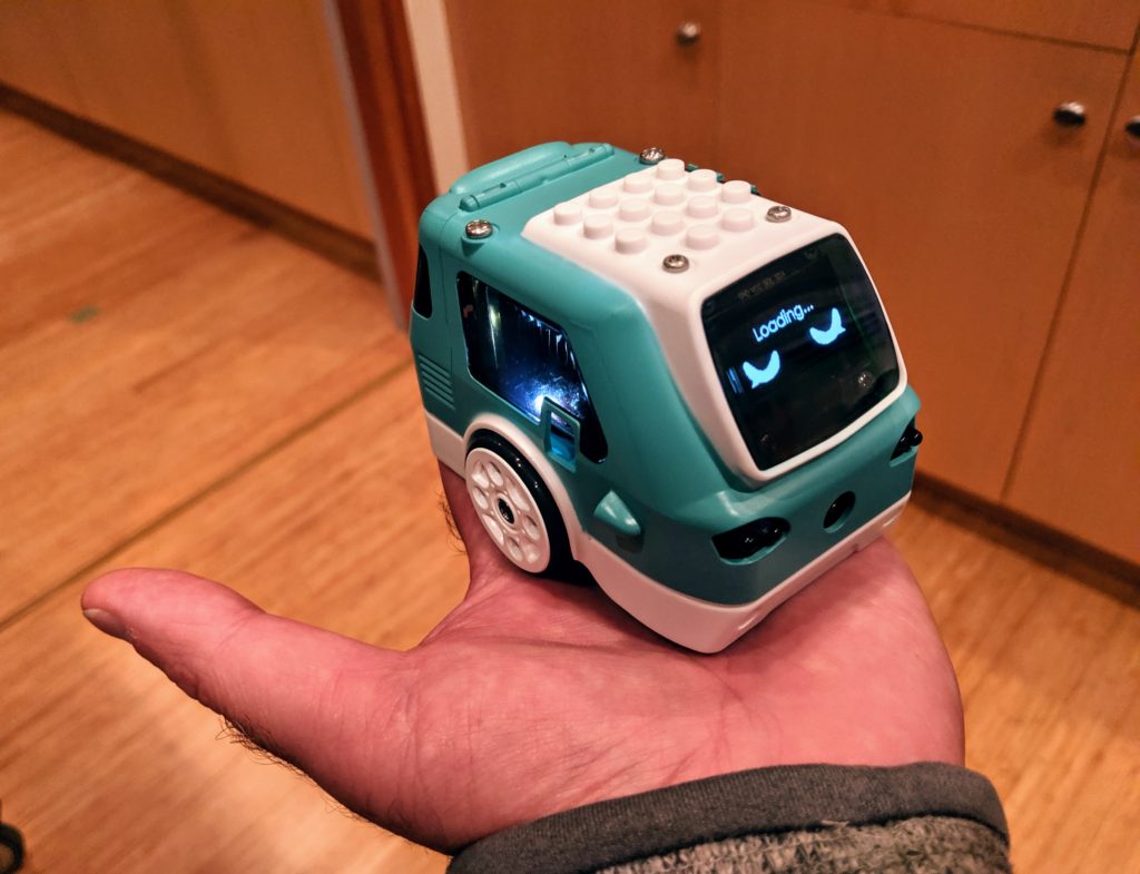
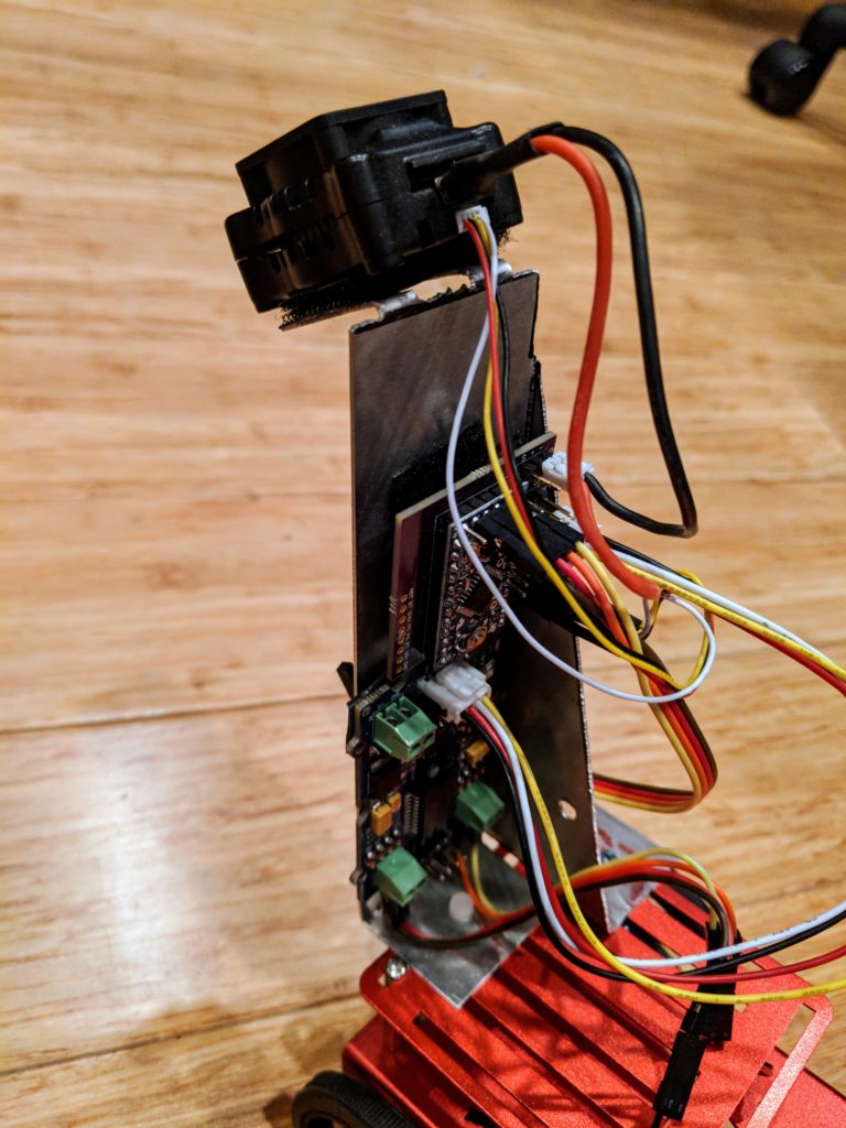
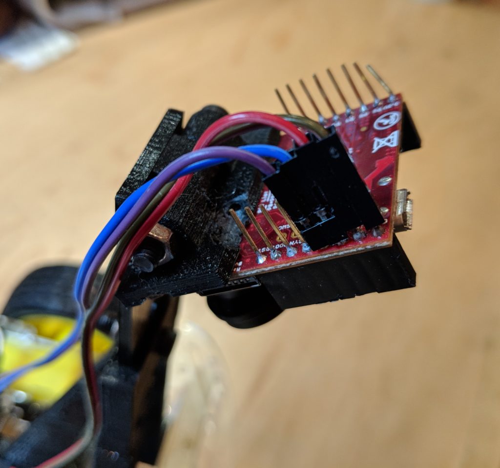
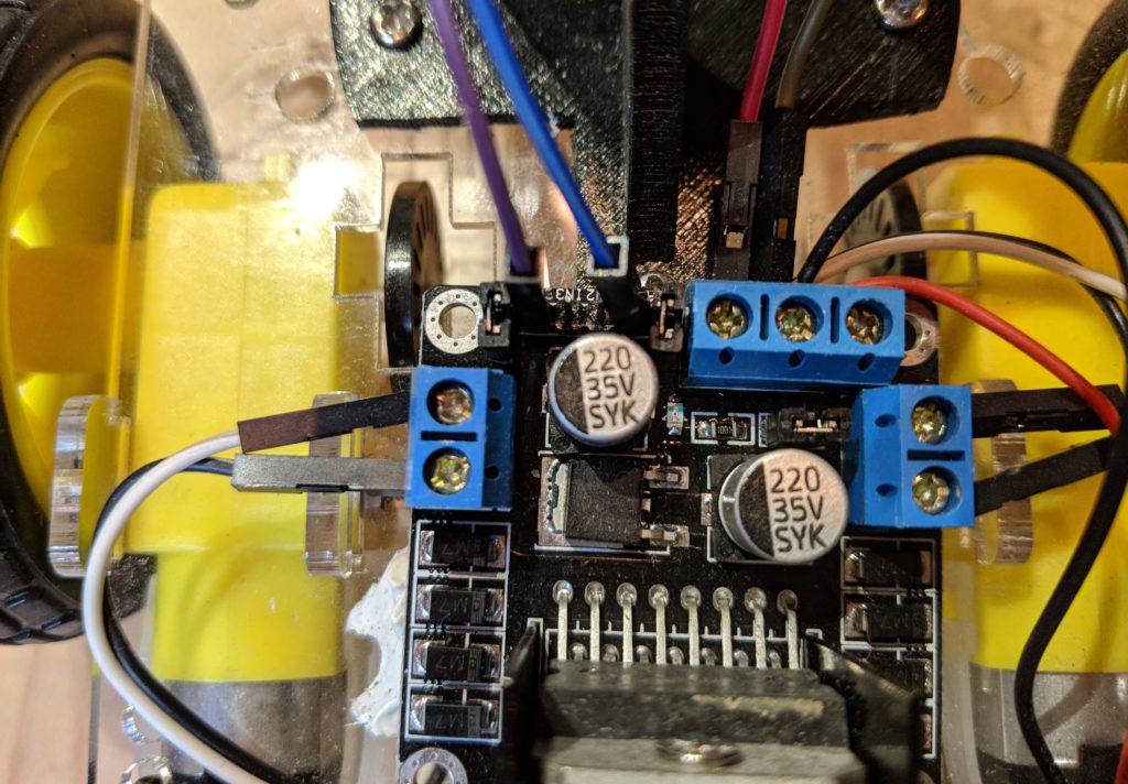
First of all, it’s ADORABLE! So small, it can fit in the palm of your hand, but has a RaspberryPi ZeroW, and Arduino, a screen, camera, loads of sensors and LEDs all inside.
Zumi started as a Kickstarter project and just shipped to first backers (I was one) last week. You can now buy it directly from its creators, Robolink, for $139. Details are here.
My first impressions were very positive, despite the usual first-batch problems with Kickstarter projects (a few missing bits in the kit and some instructions that aren’t quite accurate). It was easy to put together and once I fixed a boneheaded mistake (if you plug in the screen connector backwards, the car won’t boot at all — yikes), it booted up fine and coached me through the process of connecting via wifi and updating its firmware.
So what can it do? The initial Kickstarter pitch focused a lot on computer vision and AI, but it’s clear that many of those videos were done on beefier computers than the RaspberryPi Zero in Zumi. The current package is more limited, with no real machine learning at all.
Nevertheless, the initial lessons are a lot of fun and show the solid Python functions Robolink has shipped with Zumi. Examples start with how to use a Jupyter notebook, and then move to sensors (IR distance/obstacle, gyro and accelerometer), LEDs and the buzzer and of course motion. Although Zumi’s motors don’t have encoders, it uses the gyro to go straight and turn by set amounts, which works well.
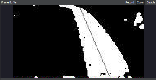
Once you get to computer vision, the limits of the RaspberryPi Zero, hobbled by the overhead of the Jupyter server and wifi streaming, show up. Lessons in object tracking, face and smile spotting and color spotting all suffer from terrible lag and several can not finish at all.
Although Robolink promises more is coming with updates, it’s hard to see how they can squeeze much more about RPi Zero using Jupyter. Although Jupyter is a great way to combine documentation, code and graphical output on one screen, it’s really designed to run on faster computers and slows to a crawl on Zumi if the camera is used. Robolink intends to release a different IDE in the future, perhaps one more like their Blockly interface, and that may work faster.
Once Robolink fixes the performance issues (perhaps by switching out Jupyter for a faster IDE) I think computer vision, including lane following and object detection, should be doable. Basic machine learning (with models trained in the cloud and only run locally) should also be possible. And who knows — maybe the Rasperry Pi Foundation will release a faster RPZero someday?
But for now, Zumi is really nicely designed and super-cute robot car at a reasonable price with a lot of room to grow.