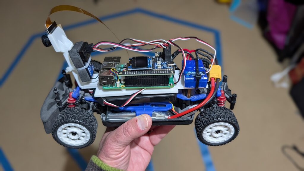
If you’re looking for a car that’s a bit smaller and easier to handle than the Exceed Magnet for Donkeycar, the 1:18th scale LaTrax Rally (https://amzn.to/45jWFDD) is great. Brushed motor, easy to add a third RC channel as an e-stop and fits the RP5 with the RC hat perfectly. You can use the RC it comes with, with no need for an I2C servo board or gamepad controller with limited range.
I designed a 3D-printable mount that fits the Pi and camera. Download it here.
If you want to add a third channel as an e-stop, you can follow the instructions here (scroll to bottom)
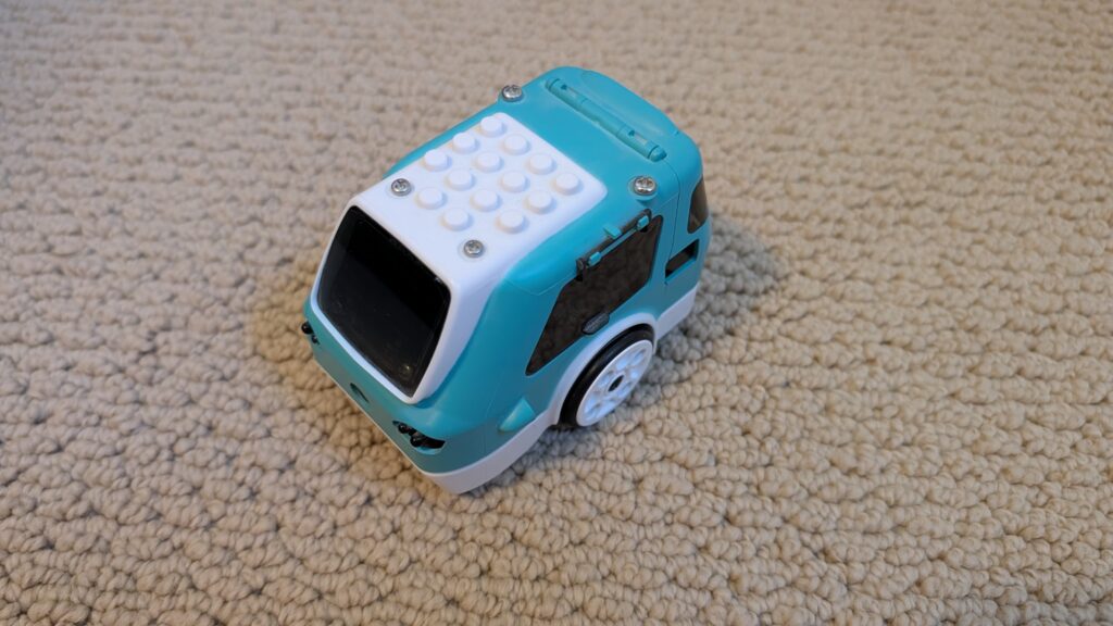
Yes, you can run Donkeycar, with a full end-to-end neural network driving autonomously, on tiny and cheap 1:28th scale cars! It’s perfect for indoors and small patios that don’t have room for bigger RC cars. Not only that, but you can use the RC controllers they come with. Here’s how to do it for less than $150:
First, you’ll need the car, a Raspberry Pi Zero 2 W and camera, a SD card (128GB or even 64GB is fine) and the Mini RC Hat. (It comes with the mount but if you have a 3D printer, you can also download this STL and print it yourself).
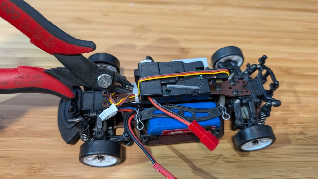
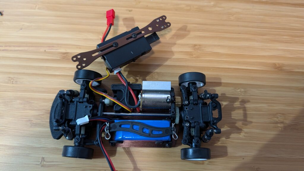
Once you have the car, take off the plastic body shell and remove the center beam as shown in the steps below. Save the screws since you’ll need them later.
First, clip off the zip tie holding in the steering servo cable
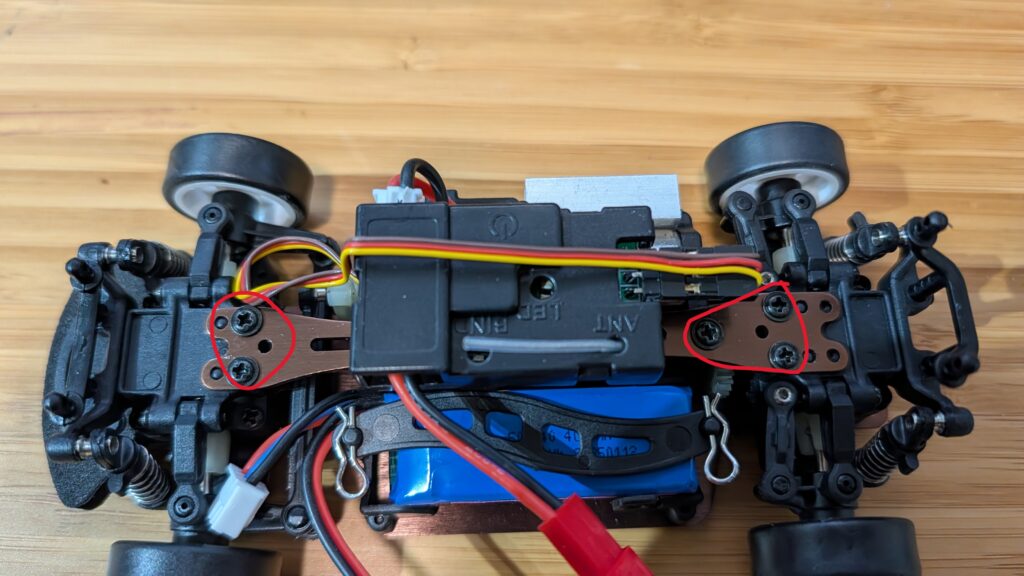
Then unscrew the screws circled in red below
Remove the center beam and unscrew the RC receiver
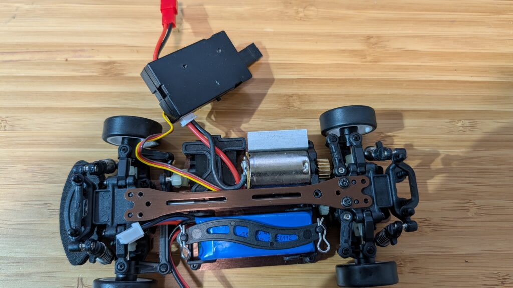
Replace the beam, just screwing in the two screws at the end. Make sure it’s seated all the way down on the little plastic posts
Screw in the Pi Zero mount using the remaining beam screws and screw in the RC receiver with the short screws that it used to mount to the beam
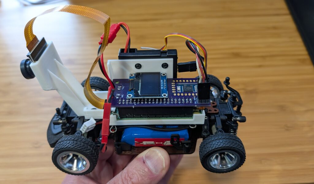
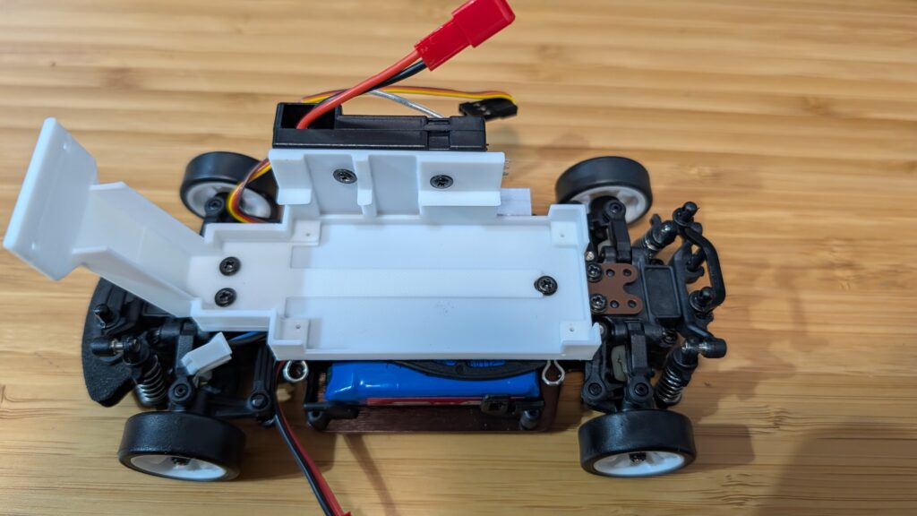
Mount the Pi Zero 2. You only need to screw it in with two screws, diagonally across from each other
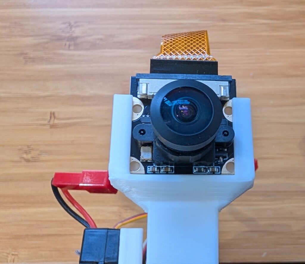
Place the camera in the mount slot, with the cable at the top.
For the software, we’ll be using an optimized version of Donkeycar that runs better on the Raspberry Pi Zero 2, which doesn’t have as much memory and compute as the Pi 5. Here’s how to load the software for that:
Step 1
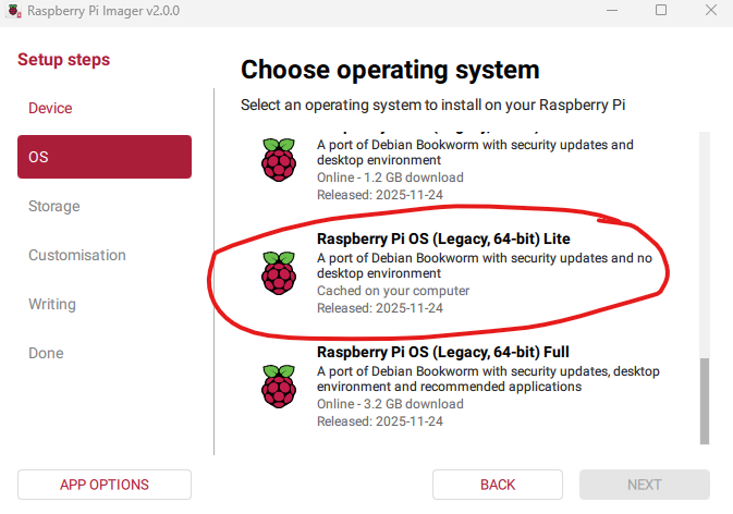
Using the Raspberry Pi Imager, select the Pi Zero 2 W as the target and for the OS, select Bookworm Lite 64 bit (Under “Raspberry Pi OS (other)”).
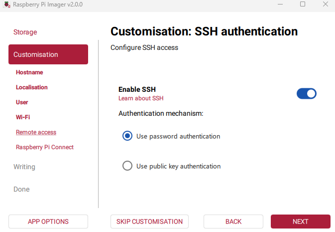
Fill out the rest of the options, including your desired name for the Pi (“donkeycar”) and your preferred username, password and Wifi details. Make sure you enable password SSH access, too:
Then write the image to card.
Step 2 Once it the SD card is done, insert it into the Pi Zero and power it on via the USB port. Once it boots up (green light stops flashing), which will take about five minutes the first time, SSH into via a terminal on your PC like this:
Then go into raspi-config (“sudo raspi-config”) and make the following changes:
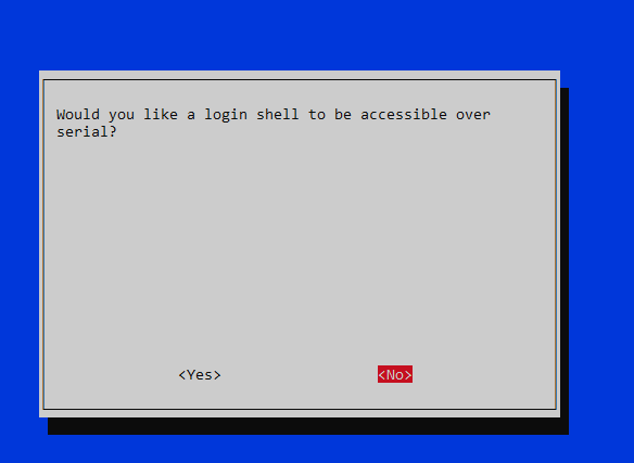
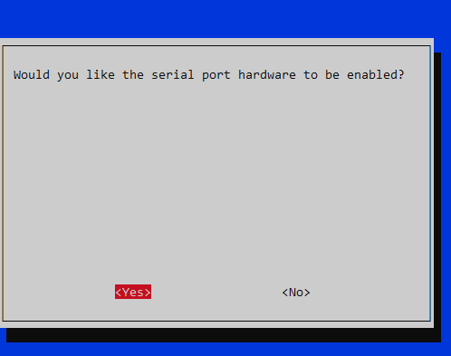
Under “Interface Options”, enable I2C and the hardware Serial Port (say “No” to the login shell being accessible over serial and “Yes” to the serial port hardware being enabled)
Under “Advanced Options” expand the filesystem
When you’re done, exit the utility and reboot.
When you log back in, enter this at the command line sudo nano /boot/firmware/config.txt In that file make two changes:
comment out “dtoverlay=vc4-kms-v3d” by putting a “#” in front of it
add this at bottom of file: “dtoverlay=disable-bt”
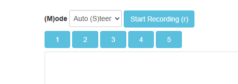
Finally, after you go through the regular recording of data with Donkeycar and then running a trained model, when you switch into auto mode with the web interface, choose “Auto (S)teer”. Because the 1:28th scale cars have an integrated RC receiver and motor controller, it’s too hard to extract the throttle signal and let Donkeycar manage it (lots of trace cutting and soldering would be required), so with these cars you control the throttle manually, while the AI controls the steering.
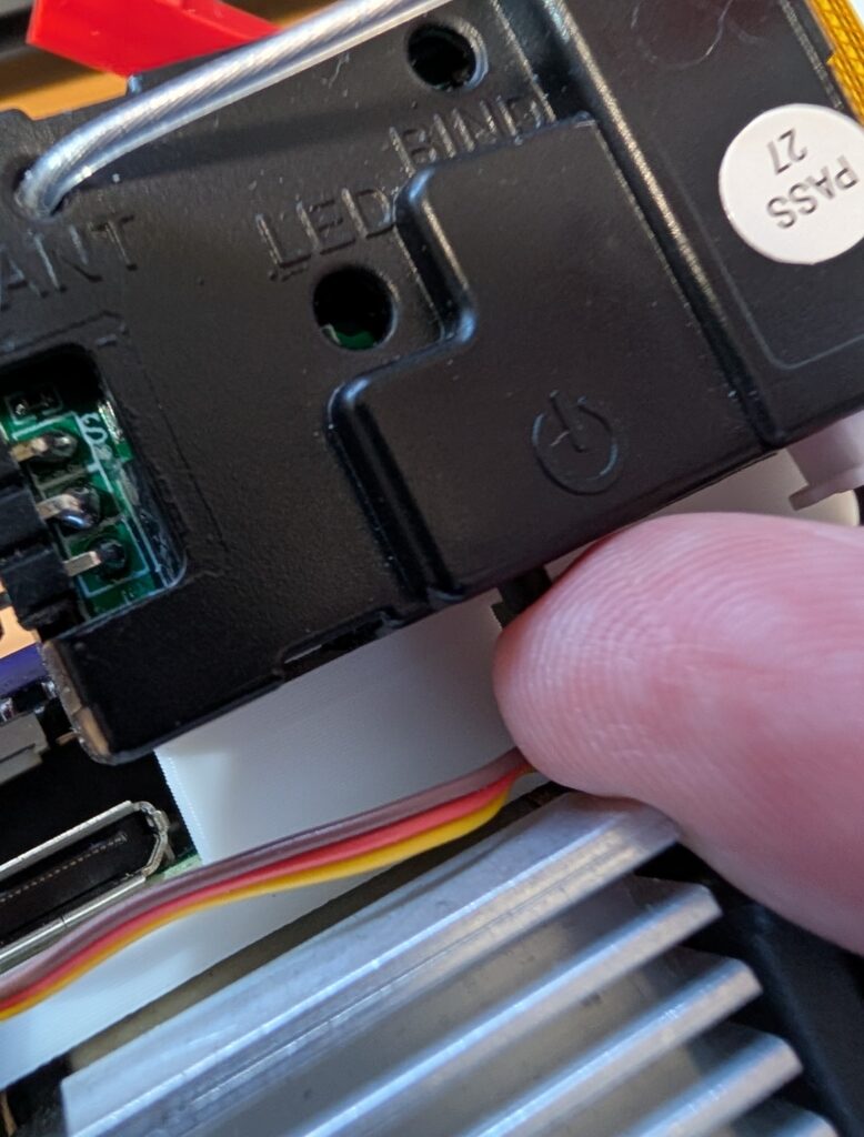
BTW, it’s not as obvious as it should be how to turn on the car. After you plug into the battery, you have to press this little button on the RC receiver, which will power on everything.
I was recently given a Quectel LG290P GNSS RTK Receiver and a Micoair LR900-F LoRa to evaluate for use as a Rover in combination with an appropriate Base Station for outdoor autonomous RC car racing. The Quectel LG290P GNSS RTK Receiver came in the form of a Sparkfun Quadband GNSS RTK Breakout Board and the Micoair LR900-F LoRa came as a two Telemetry Radio set.
The Hardware. The Quectel LG290P GNSS RTK module is a quad-band, multi-constellation, high-precision, RTK GNSS receiver. The module is capable of simultaneously receiving signals from the L1, L2, L5, and L6/E6 bands. The module has a built-in NIC anti-jamming unit which provides professional-grade interference signal detection and elimination algorithms effectively mitigating multiple narrow-band interference sources and significantly improving signal reception performance in complex electromagnetic environments. Additionally, the embedded algorithms ensure reliable positioning in complex scenarios such as urban environments and deep tree cover.
The LR900-F Telemetry Radio is a small, inexpensive radio with superior performance as a long range Telemetry Radio for the transmission of RTCM3 correction messages between the Rover and the Base Station. The LR900-F transmits in the 915MHz (890-915MHz) range, has an adjustable RF power output of up to 500mW, and uses LoRa modulation technology and frequency hopping spread spectrum to obtain excellent anti-interference performance. Additionally the LR900-F uses transparenttransmissionto to provide compatibility with any data and protocol.
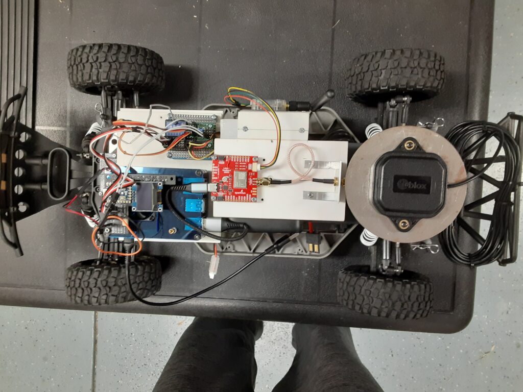
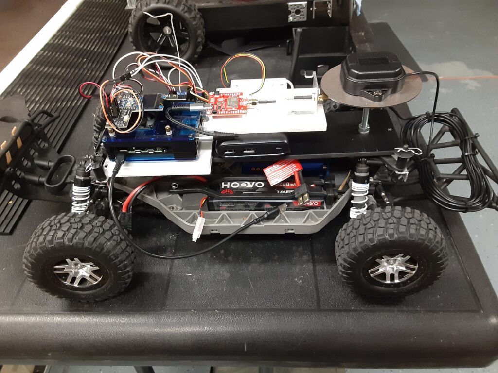
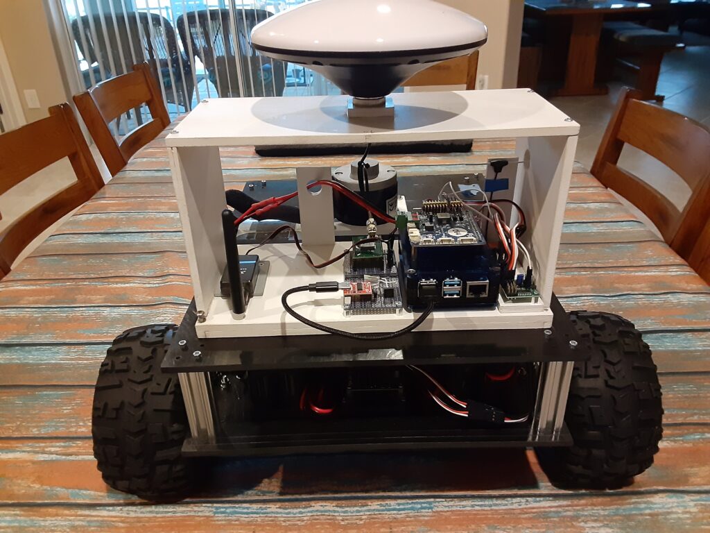
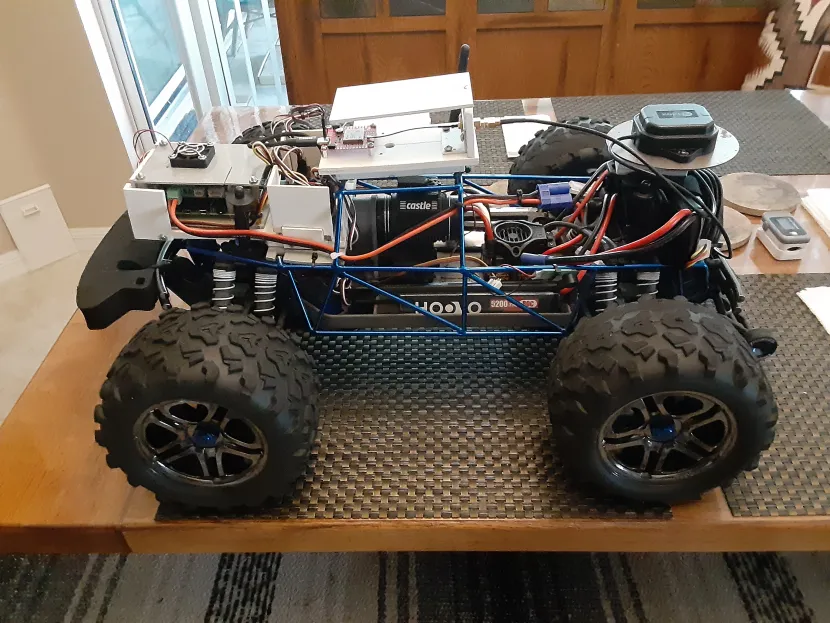
The RC Car Rover Test Vehicle is a Traxxas 1/10 scale Slash Truck chassis that started life as a 2WD BL-2 and was converted to 4WD with a brushless motor/ESC and a 4X4 conversion kit powered by a single 2S 5200mah LiPo battery. The Test Vehicle, for the purpose of this evaluation, also includes a Raspberry Pi 4B+ 4GB SBC, a Donkey Car RC HAT, a u-blox GNSS All-Band High Precision Antenna, a Fly Sky RC Receiver, and an Anker Power Core 13000 Lion battery.
ThePreparation. Prior to mounting the Sparkfun Quadband GNSS RTK Breakout Board and the Micoair LR900-F Telemetry Radio on the Slash chassis, I modified the configuration of the LG290P Receiver using the Quectel QGNSS app as follows: 1) Configured UART1 for 115200 baud. 2) Configured UART3 for 57600 baud. 3) Configured the UART1 USB output for only four pertinent NMEA messages. And modified the Micoair LR900-F LoRa using the Micoair Micoassistant app as follows: 1) Configured the Broadcast Mode for Rx only. I then mounted the Sparkfun Quadband GNSS RTK Breakout Board and the Micoair LR900-F Telemetry Radio on a sub chassis along with the Raspberry Pi 4B+/RC HAT, the u-blox precision antenna, the RC Receiver and the Anker Power Core 13000 Lion battery as shown in the photos below.
The LR900-F Telemetry Radio is connected over a four wire cable to the UART3 port on the Breakout Board while the u-blox precision antenna is connected to the SMA connector on the Breakout Board. The Sparkfun Quad band GNSS RTK Breakout Board interfaces with the Raspberry 4B+ over a USB connection.
The Evaluation. To begin the evaluation, I setup and powered up my trusty Sparkfun RTK Postcard/Portability Shield Base Station, which includes a Micoair LR900-F Telemetry Radio, in the Broadcast Tx mode for transmission of RTCM3 correction messages to the Rover, in my home’s driveway with a clear view of the sky as my autonomous vehicle test course is the neighborhood street in front of my house. I powered up the Raspberry Pi 4B+ on the Slash Rover along with the ESC and used my HP laptop to SSH into the CLI, running on the Rover’s Raspberry Pi 4B+, and changed to the mycar directory. Then I drove the Rover out into the street in front of my driveway, aligned it with a chalk line starting point as a reference, and verified that the RTK LED on the Receiver Breakout Board was a solid white indicating a RTK Fix solution. Returning to my laptop I started the path_follow.py program with python manage.py drive on the CLI, opened the Donkey Car webui using Google on the laptop, reset the car origin, hit the start recording button and used the RC transmitter to slowly drive the Rover around my neighborhood street test course collecting GPS latitude and longitude coordinates every 0.2 meters until the Rover arrived back at the chalk line origin starting point. At which time I stopped the course recording and saved the recorded course as donkey_path.csv for course playback.
The Results. Now comes the real test which is to see how well the Rover can autonomously drive the previously recorded course with P and D values based on my previous autonomous Rover experience. Using the Donkey Car webui I reset the Rover’s origin position at the starting line, selected “Full Auto”, and proceeded to watch the Rover move off of the starting line at a moderate speed, as I am using a preset PID speed value, and head straight North up the neighborhood street and make a perfect 180 degree left U turn to the other side of the street. The Rover then headed South back down the street for the next 180 degree left hand U turn at the other end of the Indy style raceway course. After completing the 180 degree left hand U turn at the end of the course, the Rover then continued North on a reasonably perfect beeline path to the start of the course so I let it continue for ten more laps without any issues like going off course and crashing into the curb.
TheConclusions. Compared to my ZED-F9P RTK GNSS Receiver equipped Traxxas E-Maxx Rover, the LG290P RTK GNSS Receiver equipped Traxxas Slash Rover appeared to negotiate the 180 degree left hand U turns with little or no overshoot compared to the E-Maxx Rover and exhibited much less straightaway course hunting than the E-Maxx Rover. However it will be interesting to see how well the E-Maxx Rover performs when equipped with a LG290P RTK GNSS Receiver which will be the subject of my next blog post. As for the performance of the Micoair LR900-F LoRa Telemetry Radios, I can definitely recommend them as I was able to drive the Slash Rover over a quarter of a mile LOS from the Base Station, with the Base Station Micoair Telemetry Radio set at MIN power output, and not lose the Base Station Telemetry Signal. Since I was running the Base Station Micoair Telemetry Radio at MIN power output, I would say that there is plenty of output power margin for farther LOS distances or challenging urban environments when running the Telemetry Radio at the MID or MAX power output settings.
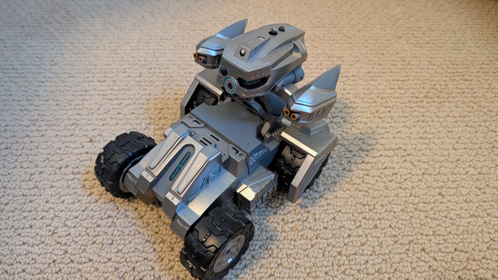
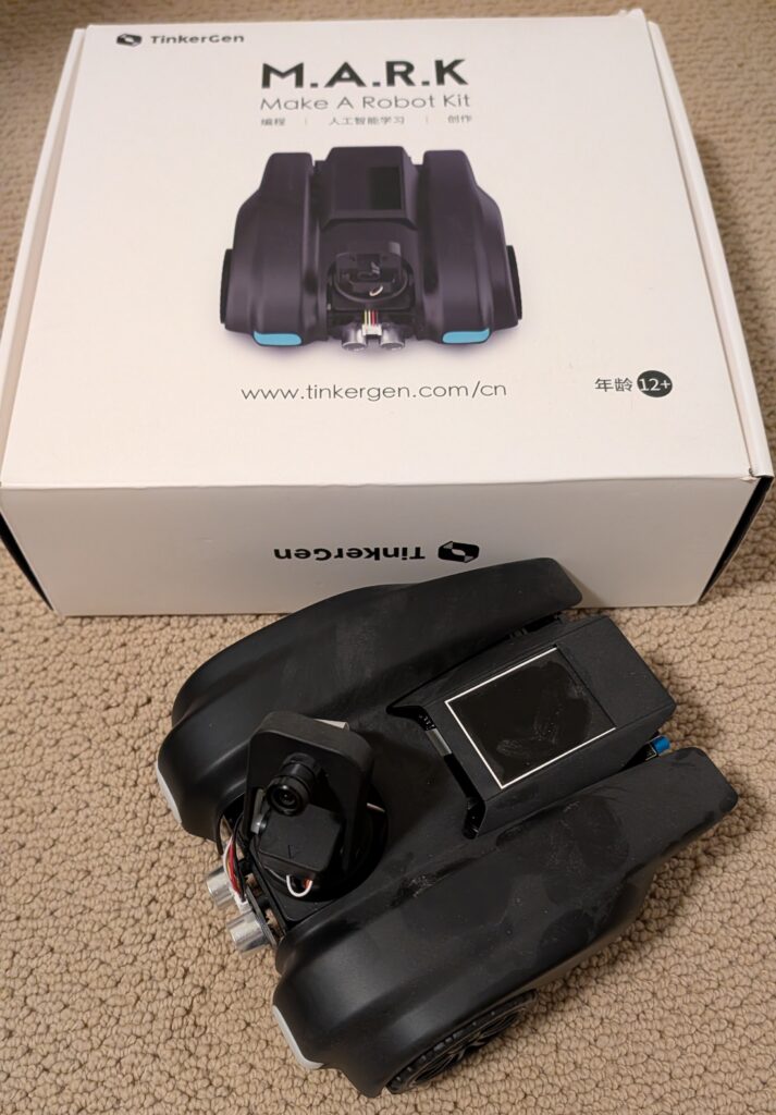
I’m clearing out my workshop and giving away a bunch of wheeled robots, all in good condition, that I won’t have time to use. These are free to a good home, but you must be willing to pick them up in the San Francisco Bay Area, either in East Bay or Palo Alto. DM me on Twitter/X or LinkedIn if you’d like something, and I’ll update the post as they go to show what’s still available.
Sadly, this is only about 30% of my collection. I may have a bit of a robot car addiction.
[now taken]
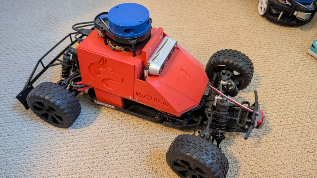
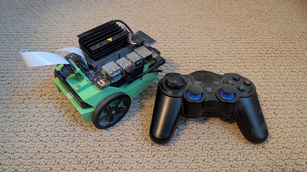
This is Musher.io, a very nice robot car with all the fixin’s from the University of Washington. It’s $1,000 worth of gear, from the Jetson Nano to the lidar, depth camera, VESC motor controller and fast and robust RC car chassis. ROS-based.
[now taken]
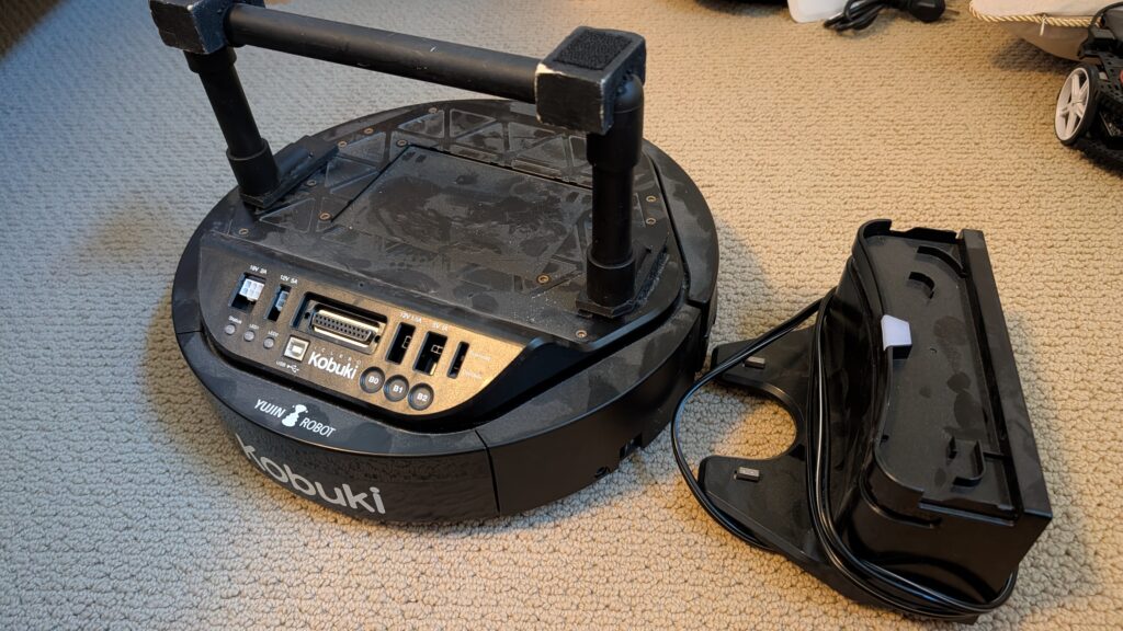
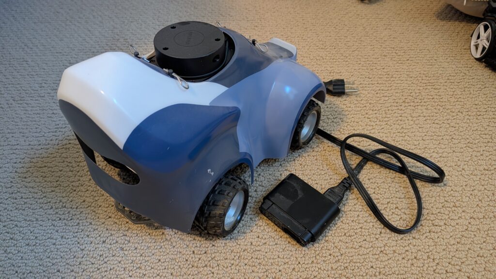
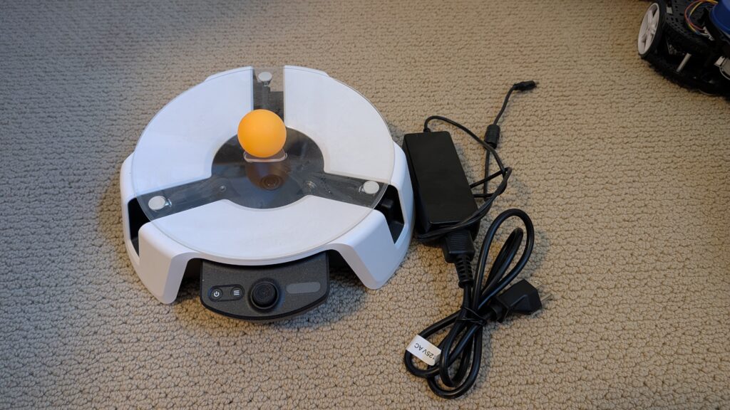
Yujin Kobuki robot platform. Like a Roomba Create, but optimized for robotics and adding sensors and actuators. Comes with recharging dock. $800 value.
[now taken]
Amazon DeepRacer with stereo cameras and lidar. Was $800 new, including add-ons. Fully loaded!
[now taken]
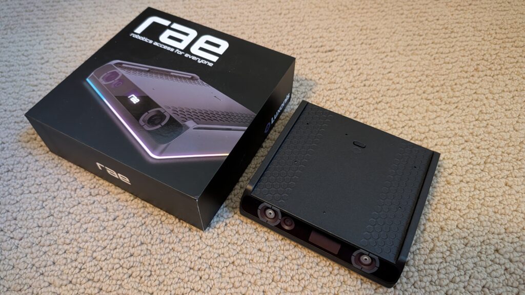
RAE robot from OpenCV with OAK depth camera. Still in the box.
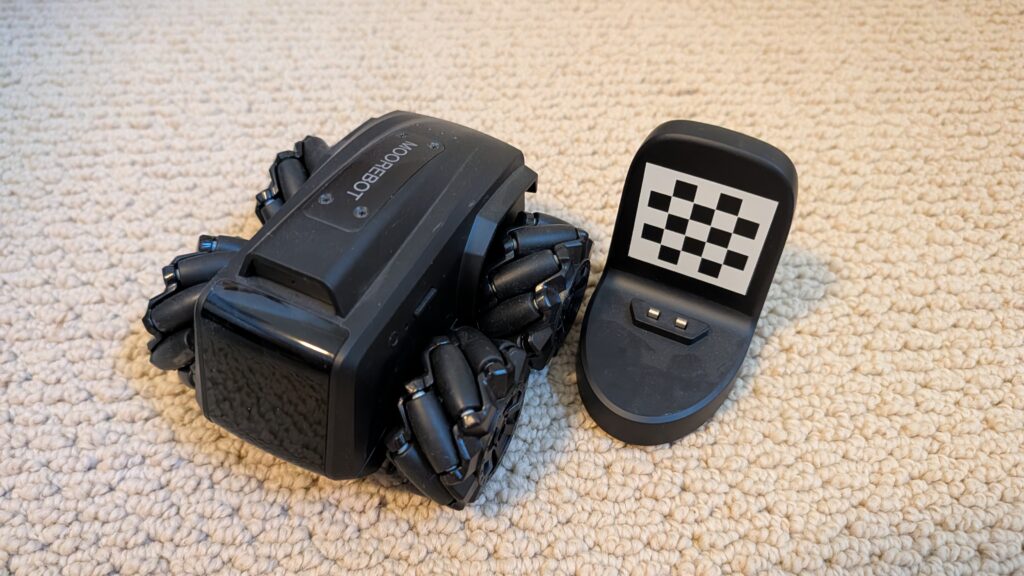
[now taken] Zumi robot car. RaspberryPi-based. Can drive along a track and even obey stop signs and signals. Adorable!
[now taken] Microsoft Project Moab balancing platform. “Teach an AI brain to balance a ball in the center of a plate using a custom simulator and sample code.” Prototype, never released! Works
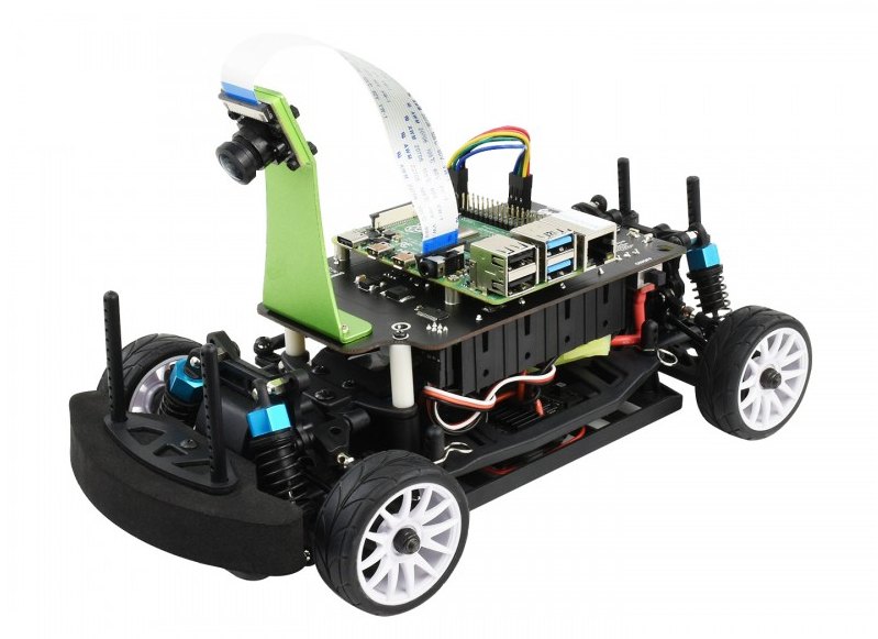
The $268 Waveshare PiRacer Pro (Waveshare, Amazon) is my favorite ready-to-run Donkeycar autonomous car, at least as far as the hardware goes. But it comes with badly outdated software, which is no longer supported by the Donkeycar project. So when you get one, the first thing you’re going to want to do is load the latest Donkeycar, which works great on that hardware.
Here are some tips on doing that.
First, install the latest RaspberryPi OS on the SD card, following these instructions.
Once you’ve done that, SSH into the Pi and after you’ve updated the OS (“sudo apt update", “sudo apt upgrade"), make sure you enable I2C using "sudo raspi-config").
Then you can you create the Donkeycar app by following these instructions.
Before you can run Donkeycar, you need to customize some settings in the myconfig.py file in your mycar directory.
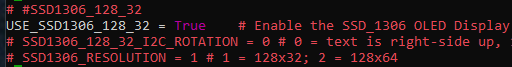
Enable the OLED screen by uncommenting this line and setting it to True (note that the OLED will only show text when you’re running Donkeycar, which you’ll do later when you’re ready to drive with “python manage.py drive“).
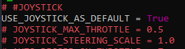
Enable the game controller that comes with the car by uncommenting and setting the Use Joystick as Default to True if is not already.
It will default to Xbox mode. To ensure that your gamepad is in Xbox mode, hold the Home button for 7 seconds after powering it on
That’s it! Your Waveshare car should be ready to train and race like any other Donkeycar. Return to the docs to learn how to do that.
(This has nothing to do with robocars but I had to post it somewhere)
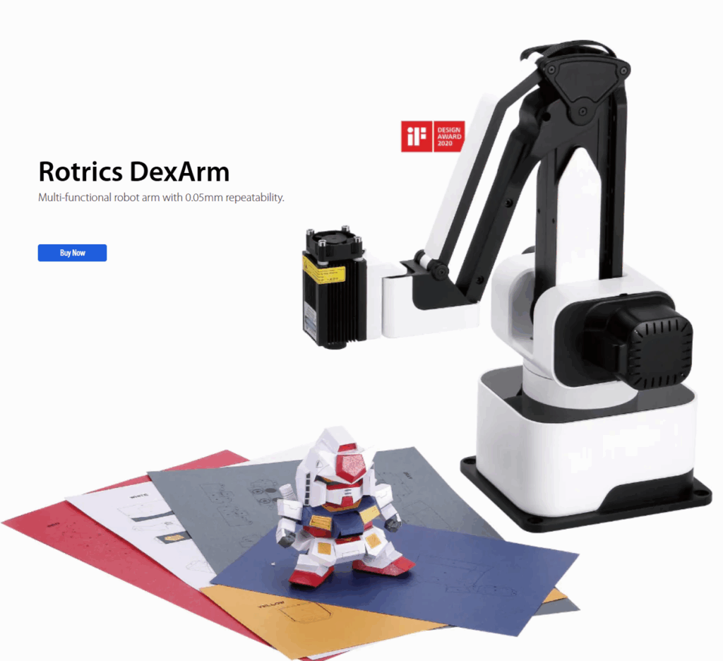
The Rotrics DexArm is a really good and cheap Chinese robot arm, which started as a Kickstarter project. I got a few of them, mostly to play around with 3D printing with multiple arms. It’s designed to do 3D printing out of the box and it’s quite good at that. It also offers rails that can allow it to move around, which are also cool. But the original promise of multiple arms being able to talk to each other and coordinate actions never really came to pass, and today although the hardware is still being sold, the software is no longer developed and the community is pretty much on its own.
Fortunately, the company sells a DIY Kit, which is supposed to allow you to add new functionality to the arm. Just what we need! Or so I thought. In truth, the DIY Kit is totally undocumented and as far as I can find, nobody has ever got it to work.
Until now! After a few days of hacking, involving scopes, logic analyzers, STM32 datasheets and digging deep in the Marlin-derivative source code to crack it
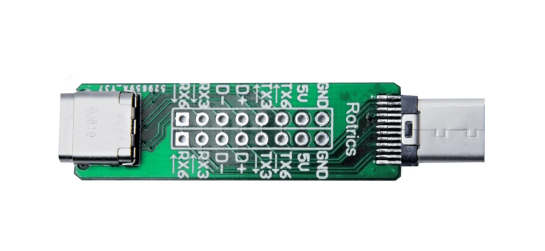
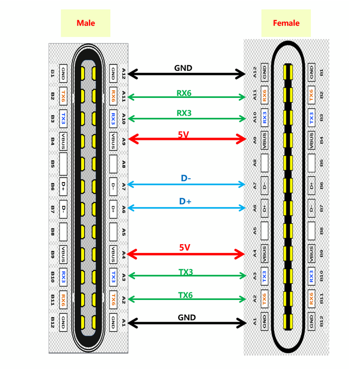
Here’s how you use it: First, the key thing to understand is that board does nothing. It’s just a USB Type C port extender. All it does is break out some of the pins of the USB port so you can get at them.
The magic is that some of the pins of the USB C port, which are typically unused, are in the case of the Rotrics arm used to send serial data from the built-in microprocessor.
So how can you use these pins? Good question! There is virtually no documentation on this, and what there is, is wrong or at least misleading (ignore all the nonsense about “PA”, “PD” or “PC” numbers that you can read here. Those are actually references to STM32F4 pins and are totally unhelpful).
Here’s the truth. The version of Marlin Rotrics uses creates two serial ports. Serial 1 goes via the regular USB and is used to communicate with the desktop app and little TFT screen the arm comes with. Serial 2 actually goes to RX3 and TX3 as shown above. As far as I know RX6 and TX6 are not actually enabled.
The way to get that data is to attach wires from the DIY Kit’s RX3 and TX3 pins and connect them to microprocessor like Arduino or a single-board-computer like RaspberryPi and read them as regular serial data.
Three important things to know:
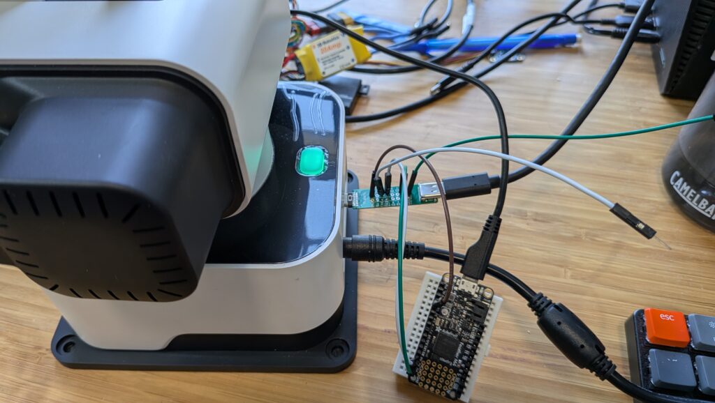
The Rotrics processor is 3.3v, so you have to read the data with a 3.3v board. An old-skool Arduino (5V) will not work. I use ESP32s or, as shown above, an Adafruit Feather M4 board. Needless to say, connect the Rotrics Tx pin to your microprocessor’s Rx pin and the Rotrics Rx pin to your microprocessor’s Tx pin as usual for serial data.
Don’t forget to also connect the GND pin on that board to a Ground pin on your microprocessor.
The data comes in at a weird 1000000 baud rate.
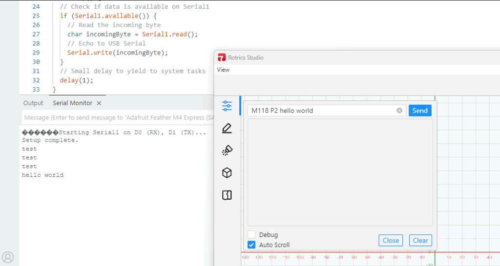
You can send data to this serial port with the Gcode command “M118 P2 [your text]”. While you’re testing, you can send that via the Rotrics Studio terminal, as I’ve shown before, but if you’re doing 3D printing you can just embed any commands you want into your Gcode after the “M118 P2” header and program your microprocessor to read the output from that serial port and act on it in whatever way you want.
I’m going to use this to add a fourth degree of freedom (the rails) to the arms as 3D printers, so my Gcode will occasionally tell the rails to move the arms (by talking to the Arduino, which in turn talks to my laptop, which in turn talks to a stepper motor-driver board) down to the next zone of a big object.
But what’s cool about this hack is that I can now add as many other commands or functions as I want, just by embedding M118 P2 [cool command] in my Gcode whenever I want and letting code on the microprocessor or my laptop deal with the rest.
A final note: If you just want the arms to send commands or text back to your laptop via the USB cable, you don’t need this DIY kit at all! Just embed M118 P2 [cool command] in your Gcode anywhere you want and it will go back to your laptop via USB serial to be read via Python (here’s an example, which reads commands from the arms and uses it to command the rails to move to a new position via a GRBL controller). Remember that you can’t be connected to Rotrics Studio while you’re reading that serial port with Python, since Studio takes the port.
If you’re converting an off-the-shelf RC car to full autonomy with Donkeycar, one of the questions you may have is why you can’t use the RC controller the car came with instead of using a Bluetooth gaming joypad. The old answer was that the RC signal has to go through the RaspberryPi and be processed or bypassed by the Python code, depending on whether you’re in manual or autonomous mode, and there’s no good way to just insert the RaspberryPi into that process (even if you could plug your RC receiver cables into the RaspberryPi, it can’t properly handle those signals nor those necessary to drive your servo or motor controller output). Thus our old advice was to throw out your RC transmitter and receiver and use the gaming joypad instead along with an I2C servo controller board.
But now we have a better answer! The new RC Hat, which plugs on top of the Raspberry Pi, allows you to use your RC transmitter and receiver as is, without needing a joypad or servo driver board. Not only does that save you money, but the RC gear has way longer range, which is great for outdoors racing or racing around lots of other cars.
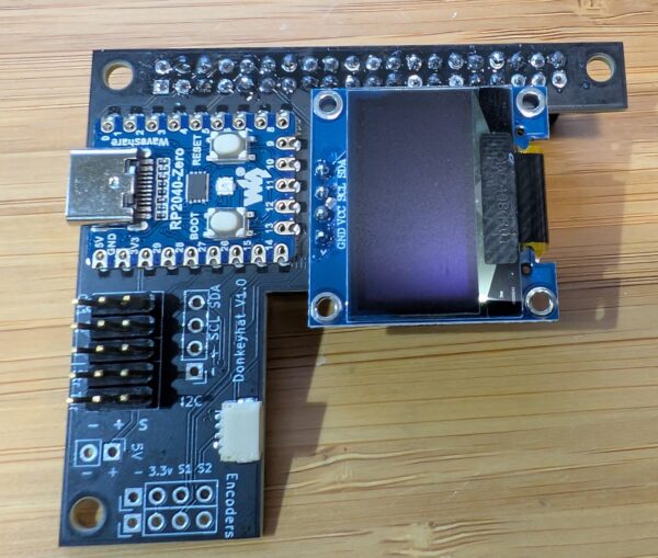
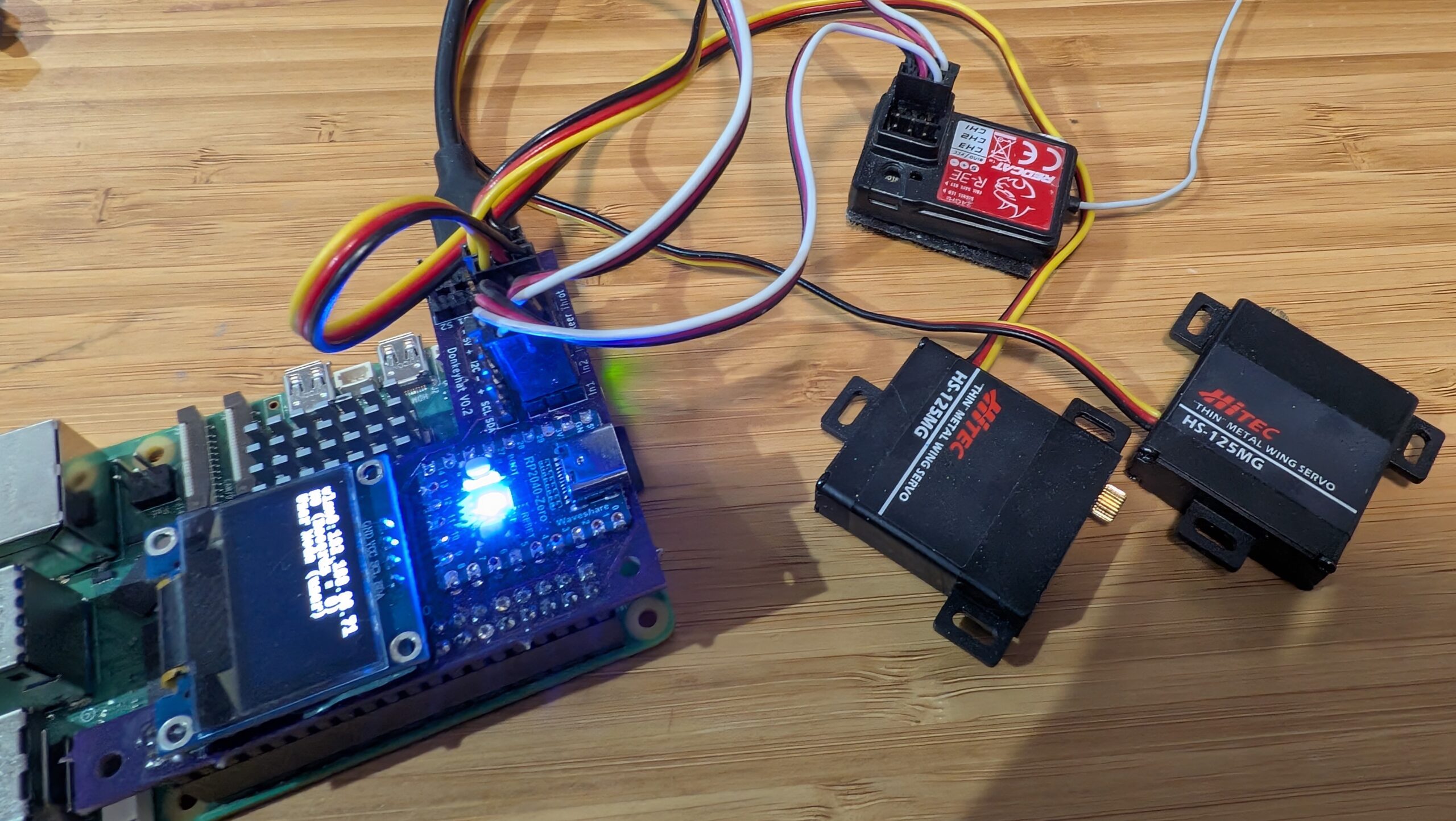
The RC hat consists of a circuit board that has a RaspberryPi 2040 Zero board on it, along with an OLED screen and the pins to plug in your RC receiver, your servos, as well as wheel encoders, other I2C devices and anything that needs 5v power. The 2040 board handles all the low-level reading of RC input and servo output and communicates with the RaspberryPi over hardware serial. The CircuitPython code for the RP2040 is here, although that’s already loaded on the board so you shouldn’t need to mess with it.
Simply use female-to-female 3-wire RC cables to connect your RC receiver into the “In 1”, “In 2” and (if you have a third channel) “In 3” pin headers. Plug your steering servo into “Steer” and your motor controller/ESC into “Throt”. Make sure you get the orientations right — black (ground) should always be on the outside next to the board edge.
To use it the hat, you’ll need to edit your myconfig.py file in your mycar directory. Make the following changes:
To enable the OLED screen, uncomment these lines and change the values as shown in the relevant areas of the myconfig.py file:
USE_SSD1306_128_32 = TrueSSD1306_RESOLUTION = 2
To enable the RC hat as output, in the “Drive train” section, uncomment and edit to this:
DRIVE_TRAIN_TYPE = "MM1"
To enable the RC hat as input, in the “Joystick” section, uncomment and edit to this:
In the “Robohat MM1 controller” section, uncomment and edit to this:
MM1_SERIAL_PORT = '/dev/ttyAMA0'
Since you probably only have 2 or 3 channels on your RC gear, all other commands and mode changes will be done via the web interface (on joypads you use dedicated buttons) via Wifi. Instructions for that are here.
The screen will come on and show the Donkey state when you start Donkey via the usual “python manage.py drive” command. It won’t be on when you’re not running Donkey, although it’s there to be used for other programs if you’d like (it’s just a standard I2C OLED screen and can be used with this Python library).
Finally, you’ll have to enable the hardware serial on the Pi. You can do this with “sudo raspi-config" Interface Options/Serial Port, which you will have already used to enable the I2C interface when setting up donkey.
If you’re using a RaspberryPi 5, that all you need to do. If you’re using a RaspberryPi 3 or 4 (or Pi Zero 2), which weirdly share the hardware serial and Bluetooth interfaces, you need to do one more thing:
You can either use “ttyS0” as the serial port in the “MM1_SERIAL_PORT” setting in your Donkeycar myconfig.py file (instead of “ttyAMA0” as described above). This should work fine, but the baud rate can vary a bit with clock speed with this approach. That hasn’t shown itself to be a problem in practice, but if you want to be safer, you can disable the Bluetooth and use the HW serial as intended at ttyAMA0:
Add this to the bottom of config.txt (enter “sudo nano /boot/firmware/config.txt"):
dtoverlay=disable-bt
Type Ctrl-O, Ctrl-X to save and exit the Nano editor
Whoa, wait a minute! Isn’t this a Robo Car website? True, but wouldn’t it be nice to have an autonomous lawnmower to save you from spending time mowing your lawn and therefore give you more free time to do RC Car racing? If so, read on to give you an idea of how I built my low budget prototype autonomous robotic lawnmower, but please remember this is just a guide and none of this design is set in stone.
Warning! This article describes the process of building an autonomous lawn mower for your entertainment and scientific inquiry. THIS IS NOT AN INSTRUCTION MANUAL OR GUIDE FOR BUILDING AUTONOMOUS MOWERS. IF YOU DECIDE TO BUILD ANYTHING YOU ARE DOING SO AT YOUR OWN RISK. A full size autonomous lawnmower, like this one, can be a VERY DANGEROUS machine — please consider carefully the implications before even thinking about building a machine like that. If you plan on building a self-driving mower you are doing so at your own risk.
Additionally, ArduPilot’s Developer Code of Conduct explicitly excludes ArduPilot from running systems where ArduPilot is effectively in control of human lives.
If you do a search on the IoT for “diy autonomous robotic lawnmowers” you will come across a vast selection of diy autonomous robotic lawnmower articles ranging from simple and inexpensive to very complex and very costly. Basically autonomous robotic lawnmowers have been around for quite a while and were kept within the lawn cutting area by sensing a wire buried around the perimeter of the cutting area of interest. However, now that GPS and especially RTK GPS guidance controllers have come into the hobbyist price range, building an autonomous robotic lawnmower using RTK GPS guidance has become a reality. Whereas the wire sensing autonomous robotic lawnmowers usually followed a random cutting pattern, sometimes cutting the same cutting area multiple times, the RTK GPS guided autonomous robotic lawnmowers can be programmed to meticulously cut a nonrepeating swath of grass row after row until the lawn is completely mowed. Still interested? Now on to the nuts and bolts of building an autonomous robotic lawnmower.
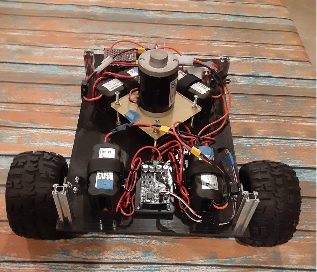
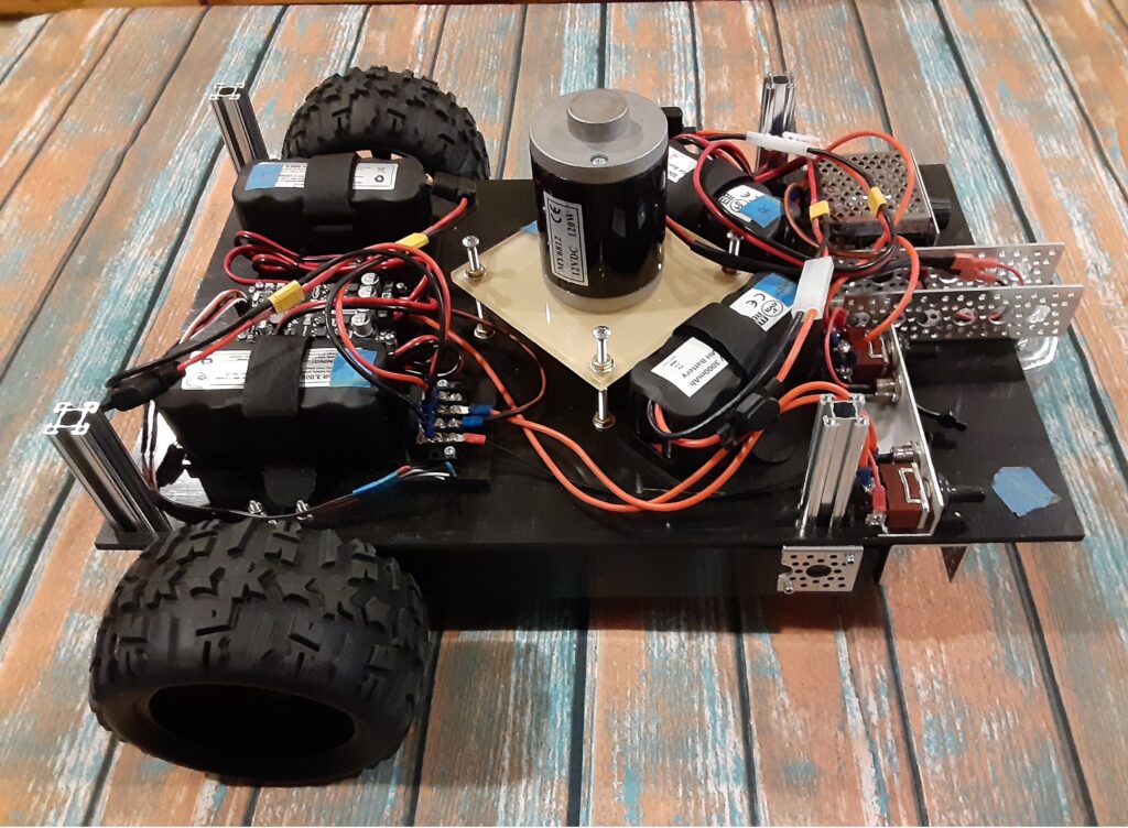
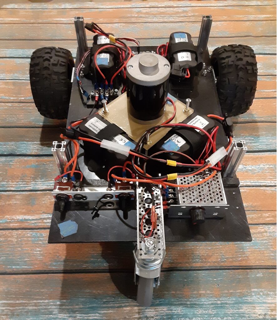
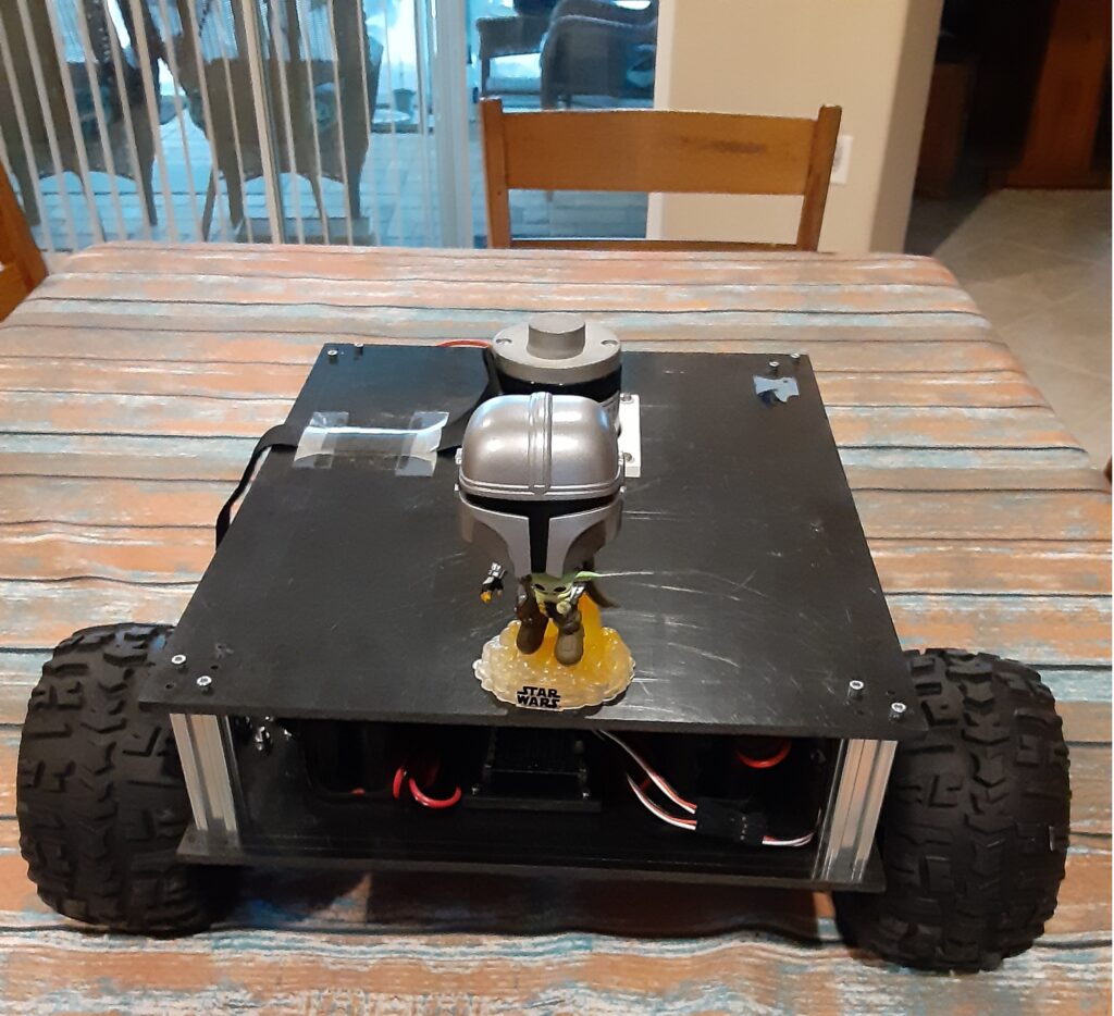
The typical autonomous robotic lawnmower is usually composed of a chassis, some form of motive power, a cutting head, a power source, and some form of cutting path guidance. I chose 1/4 inch thick black ABS plastic sheets to build the chassis which consists of two plates one 19 inches X 12 inches and the other smaller plate 15 inches X 12 inches. The larger plate serves as the mounting point for the differential steering motor controller, the drive motors, the cutting head motor, the batteries, the power switches, and a speed controller for the cutting head motor. The three photos below show how I positioned the aforementioned components on the main 19 inches X 12 inches plate. The smaller plate is attached to the main chassis plate with 72mm long 1109 Series goRAIL, one in each corner using appropriate metric hardware, to provide a mounting surface for the RTK GPS Path Guidance Module as shown in the fifth photo below.
The differential steering motor controller receives steering and throttle PWM signals from the RTK GPS Path Guidance Module and converts those PWM signals to differential steering and throttle voltages to control the two 12vdc drive motors.
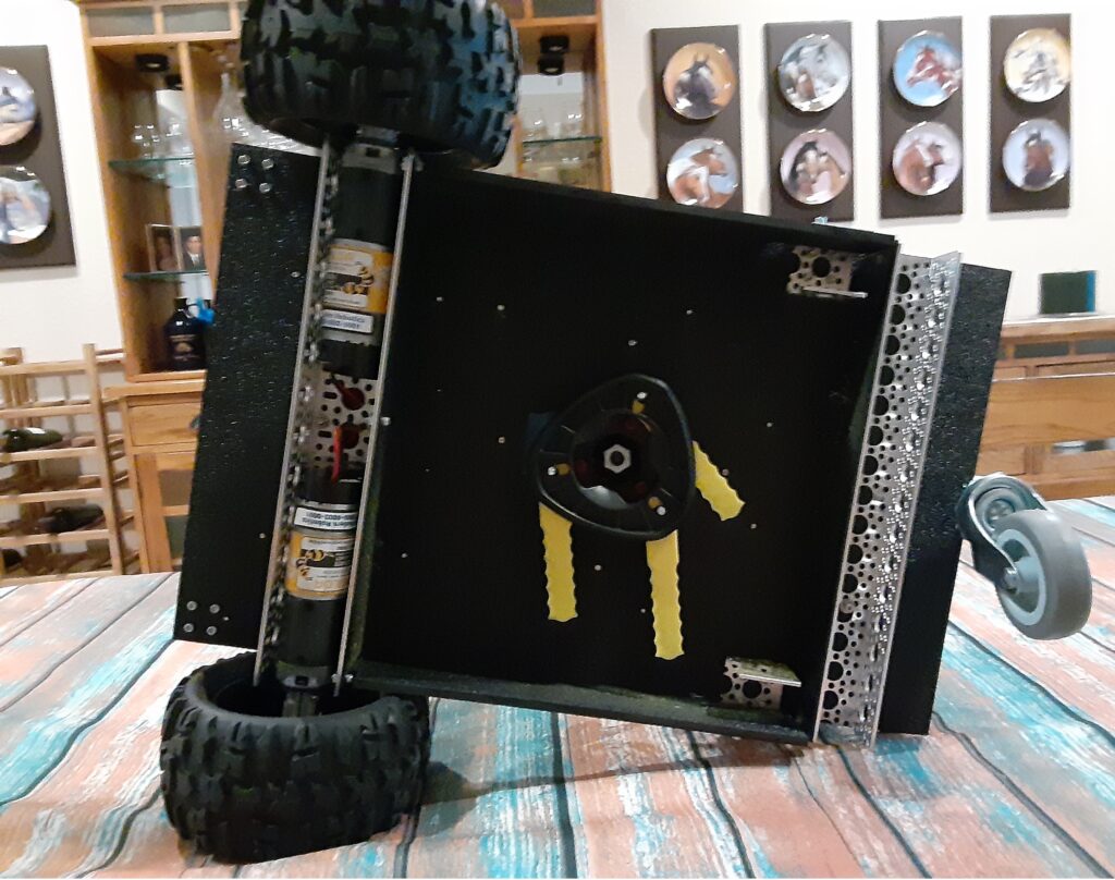
The cutting head motor shaft of 8 mm in diameter is connected to the cutting head with a 8 mm to 10 mm threaded shaft adapter who’s threaded 10 mm shaft conveniently fits the mounting hole in the cutting head. The cutting head motor, as seen in the three photos below, is mounted on its own vertically adjustable platform with its threaded shaft adapter penetrating the main chassis plate to couple with cutting head on the underside of the main chassis plate as shown in the fourth photo below.
The two sets of 12vdc battery pairs, seen in the three photos below, provide power to the differential steering motor controller which powers the drive motors and the speed controller that powers the cutting head motor. I chose 12vdc NiMH 3amp-hr batteries because they do not have to be removed from the chassis to be charged as would LiPo batteries that require a balancing charger. Additionally the NiMH batteries are heavy, compared to a LiPo battery, and help provide additional weight that keeps the chassis moving smoothly over thick grass.
The power switches, seen on the left in photo three below, are a pair of SPDT with center OFF switches which allows me to either use the switches to provide battery power to the differential steering motor controller or the cutting head motor speed controller or charge the two sets of battery pairs through their respective charging ports adjacent to each power switch.
Since DC motors draw the most current at stall or when first turned on, I decided to power the cutting head motor with a variable PWM speed controller which can be seen on the right in photo three below. Employing this type of controller allows me to switch on the cutting head motor and gradually bring it up to the desired cutting head speed which protects the 12vdc NiMH batteries from a high current surge when starting the cutting head motor.
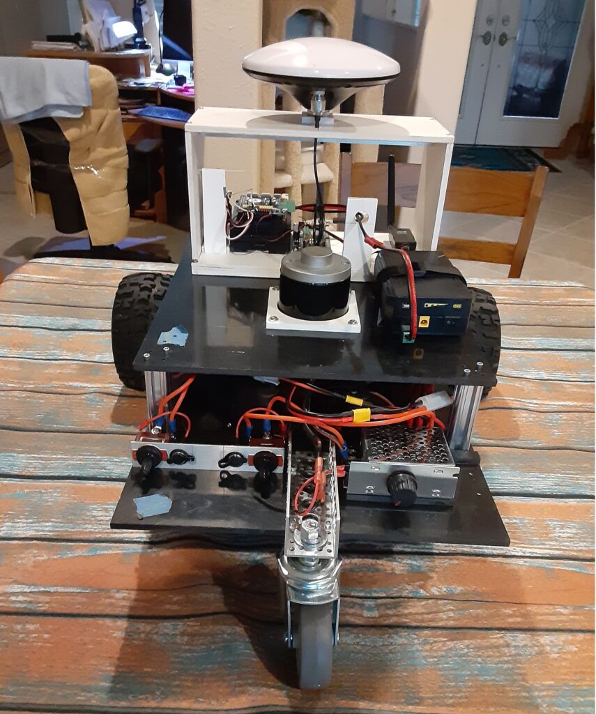
Okay, now that we have the lawnmower chassis put together, how are we going to program the mower to meticulously cut a nonrepeating swath of grass row after row until the lawn is completely mowed? This is where the RTK GPS Guidance Module comes in to play. You can build your Guidance Module as you see fit. Basically the Module should include a RTK GPS module, GPS L1/L2 antenna, Telemetry radio compatible with the Base Station telemetry radio, a Single Board Computer (SBC), a RC receiver, as a minimum. If you like using ArduRover/Mavlink for controlling your lawnmower, you can use a Pixhawk 2.1 as your SBC and add the necessary RC receiver and telemetry radio and RTK GPS module.
My Lawnmower Guidance Module employs an RTK GPS module that provides RTCM corrected X and Y position coordinates to an appropriate Single Board Computer (SBC) running the DC path_follow template which is used to record and playback a mowing path sequence over the lawn cutting area of interest. Using a RC transmitter to control the lawnmower steering and throttle through a RC receiver attached to the SBC through an RC Mux, I recorded the row by row path that I wanted the lawnmower to cut the grass in the area of interest while in the User Mode. Placing the lawnmower back at the start of the recorded path, I then set the RC Mux to use the output of the SBC for steering and throttle guidance, instead of the RC transmitter, put the lawnmower in the Full Auto mode and watched it repeat the previously recorded path. Yes, I know that this is kind of a primitive way to record and playback the recorded mowing path compared to using ArduRover/Mavlink, but hey, this is a budget build.
Comments or questions? Please post below.
Main Chassis Front View (1)
Main Chassis Side View (2)
Main Chassis Rear View (3)
Main Chassis Bottom View (4)
Chassis Upper Mounting Plate with Bobble Head Mandalorian and Baby Yoda (5)
Rear of RTK GPS Guidance Module on upper Chassis (6)
Even though RTK GPS hardware has come down in price substantially over the last couple of years, building a RTK GPS Base Station is still not inexpensive for the average RC Car enthusiast. However there is hope and I will show how a barebones Base Station can be built at a reasonable out of pocket cost.
The cost of the Base Station I described and built in my recent Blog post Using the Donkey Car Path_Follow Template with RTK GPS pencils out to around $580 (plus shipping for some of the parts) which puts it over $600. This barebones Base Station can be built for under $400. Interested? Then read on.
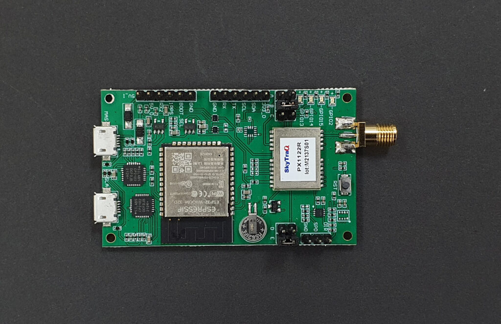
The Barebones Base Station, unlike my original Base Station, integrates the RTK GPS module with the ESP32 WROOM processor and does away with the LCD Display, but retains the Sparkfun L1/L2/L5 Survey Grade antenna (for future proof operation) and the Sik telemetry radio for RTCM message transmission to the Rover. The integrated RTK GPS module/Processor (PX1122R L1/L2 RTK Evaluation Board shown above) comes from the NavSpark Store in Taiwan and can be found here on the store website. Before you get all excited about the low price of $95 compared to the Sparkfun ZED-F9P RTK GPS module, just remember that the module is being shipped from Taiwan by FedEx air which, in my case added $55 to the cost of the module as I live on the US East Coast, will probably run between $50-$60 depending on where you live. Obviously the closer to Taiwan that you live, the cheaper the FedEx shipping will be. I queried the NavSpark Store as to a possible US distributor, but it was a no-go as they said that the overhead was too high to make a reasonable profit. Bummer to say the least.
Before moving on to the programming and evaluation of the PX1122R L1/L2 RTK Evaluation Board, a word about the Sparkfun L1/L2/L5 Survey Grade antenna. The L5 band upgrade is preoperational and should be fully in place by 2027 so the Sparkfun antenna should future proof your Base Station as RTK GPS modules that support the L1/L2/L5 bands become available. However there is a cheaper L1/L2 Survey Grade antenna that can be found here for $78. I have tested this Beitian BT-160 on a NavSpark Store PX1122R Breakout Board and it provided performance comparable to the Sparkfun Survey Grade antenna for about $50 less.
The programming of the PX1122R L1/L2 RTK Evaluation Board can be accomplished by following the steps in the Getting Started with PX1122R RTK Evaluation Board to install the Windows GNSS Viewer on page 3 and for setting up the EVB as a Base Station (2/3) using the Survey Mode on page 10. Based on my experience with the Sparkfun ZED-F9P using the survey-in mode, I recommend a Survey Time of 600 (sec) and a Standard Deviation value of 30 (cm) though other users seem to like the default values of a Survey Time of 60 (sec) and a Standard Deviation value of 30 (cm).
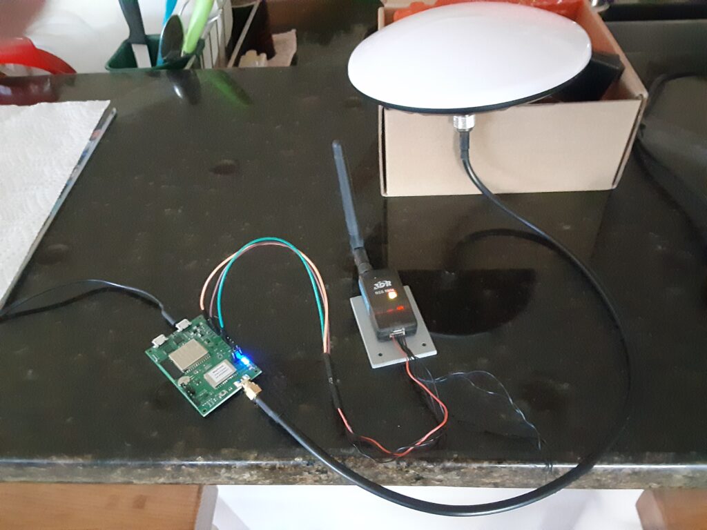
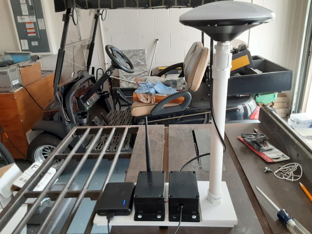
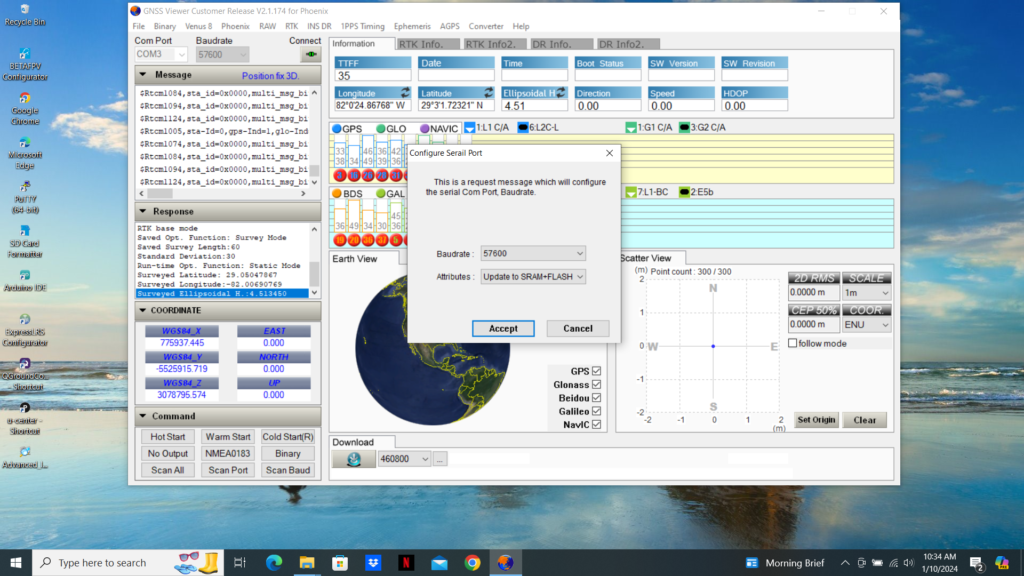
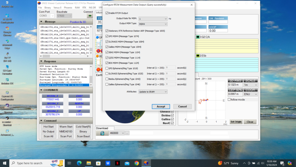
Now is the time to select a suitable enclosure for the Evaluation Board (EVB) and attach the Sik telemetry Radio and suitable Survey Grade Antenna as seen without an enclosure in my prototype photo below and the completed Base Station in the second photo below. The Very Quick Short Baseline Test (1/2) on page 13 can be used to determine the location of the TX, GND, and 5V_O pins on the EVB that should be connected to the Sik telemetry radio to transmit the RTCM correction messages to the Rover. The EVB TX pin should be connected to the RX (2) on the Sik telemetry radio while the GND and 5V_O connect to the Sik telemetry radio Ground (6) and the Power (1) respectively. The EVB TX pin must be set to 57,600 baud as shown in the third photo below. Unfortunately the NavSpark Store designers did not use a separate UART to transmit RTCM correction messages, like Sparkfun does, so the USB1 and the TX/RX UART must be the same rate of 56,700 baud. This should not create a problem since the RTCM correction messages being output on USB1 are for observation only with the GNSS Viewer therefore speed is not an issue. The only item left now is to verify the RTCM correction message output. This can be accomplished by clicking on the GNSS Viewer RAW tab and selecting “Configure RTCM Measurement Data Out” as shown in the fourth photo below. Since the “RTCM Measurement Data Out” default configuration was very similar to the Sparkfun recommended configuration for the ZED-F9P Base Station, I left them as is. If you decide to make changes to the “RTCM Measurement Data Out” default configuration, make sure you select “Update to SRAM+Flash and then hit the “Accept” button.
Prototype Base StationCompleted Base StationConfigure TX Baud RateConfigure RTCM Measurement Data Out
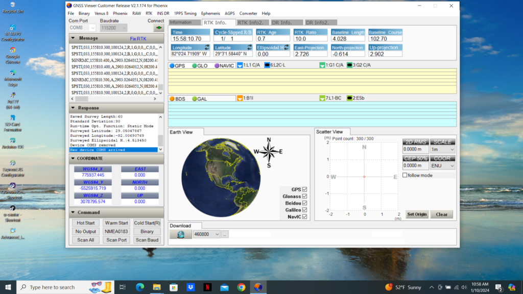
Now comes the proof of the pudding so to speak. I started up the PX1122R L1/L2 RTK Breakout Board located on my DC Lawnmower Rover by plugging the Breakout Board Sparkfun UART to USB converter output to my trusty laptop running the GNSS Viewer. I then plugged the Base Station Evaluation Board USB1 output into a suitable 5 vdc supply and watched the PX1122R L1/L2 RTK Breakout Board GNSS Viewer output shift from “Position fix 2D” in the Message Bar to “Float RTK” and finally to “Fix RTK” (see photo below) once the Base Station Evaluation Board has completed its Survey Mode and began transmitting RTCM correction messages to the Rover Breakout Board. If you are using a Sparkfun ZED-F9P RTK GPS module on your Rover, you should see the module RTK yellow LED go from solid yellow to flashing yellow (Float) and finally go out completely (Fix) once the Base Station has completed the Survey Mode and a Fix solution is reached.
Almost three years ago zlite contributed a blog post titled “Using ArduRover with an RTK GPS“. It was an excellent article that detailed using existing RTK GPS hardware available at the time to provide RC Car course guidance using ArduRover with a Base Station/Rover RTK GPS configuration. In this blog post I will detail how to use the Donkey Car Path_Follow template with RTK GPS hardware.
The Donkey Car Path_Follow template can be configured to use either wheel encoders or GPS to record a path and then have the RC Car autonomously track the recorded path from beginning to finish. For those of you who are not familiar with Donkey Car, the official website with instructions on how to build, configure, drive and then train a RC Car using either the Raspberry Pi or NVIDIA Nano 4GB Single Board Computers (SBC) can be viewed here. This article assumes that the user has already built their RC Car, programmed the selected SBC with an appropriate Operating System (OS), the Donkey Car app, created the car application using the path_follow template and is ready to procure, install, and program the necessary RTK GPS hardware.
There are presently two solutions to using RTK GPS hardware with the path_follow template car application with one being less expensive than the other. Both solutions require a Rover RTK GPS module and an appropriate antenna for the car, but then deviate as to from where the required course corrections for the Rover are received. The more expensive approach requires either the purchase or construction of a RTK GPS Base Station while the cheaper solution uses Internet-based corrections instead of a local base. A detailed tutorial, by Donkey Car Maintainer Ezward, on using the Internet-based corrections solution can be found here, while the rest of this blog post will be devoted to describing either purchasing or building a suitable RTK GPS Base Station, a telemetry system to communicate with the Rover, and the Rover RTK GPS module/antenna.
For those users with deep pockets, a ready built RTK GPS Base Station can be procured from Sparkfun.com here. For those of you who like to roll your own to build a Base Station, as I did, here are the steps I took to build a Base Station which assumes you know how to use the U-Blox U-Center, are proficient with the Arduino IDE, and have good soldering skills.
For a start, here is a list of the required hardware for the Base Station that I built:
To configure the Base Station Sparkfun ZED-F9P RTK GPS module I followed the detailed steps in the Sparkfun “Setting up a Rover Base RTK System” tutorial with the following exceptions:
I did not complete the initiation of the survey-in mode section of the tutorial because the ZED-F9P will not go into the survey-in mode from a cold start.
I did not attach the first Sik telemetry radio to the ZED-F9P because I wanted to power the telemetry radio with 5 vdc which is not available on the Qwiic interconnection bus.
See below how I programmed the Sparkfun Thing Plus to put the ZED-F9P into the survey-in mode from a cold start.
How to put the ZED-F9P into the survey-in mode from a cold start:
Follow the Sparkfun ESP32 Thing Plus (USB-C) Hookup Guide to program the Thing Plus with the Example4 .ino code which has bee updated since I worked with it. a) A “delay(5000)” code has been removed from the lcd.print statements which means messages will just flash by on the LCD display.
I made the following changes to the Example4 .ino code:
a) I changed the code at line 52 to Serial1.begin(57600) to let the ESP32 Thing Plus Serial1 port transmit the RTCM correction messages.
b) I commented out the code at lines 81 and 82 because I am using the ESP32 Thing Plus Serial1 to transmit the RTCM correction messages over the telemetry link.
c) I commented out the following section of code: line 85 to line 105 because those CFG values were previously configured during the “Setting up a Rover Base RTK System” tutorial.
d) At line 129 I changed the 60 sec and 5.0 m to 600 sec and 1.0 m and usually get a position accuracy of under 0.7 m after 600 sec on a clear day.
e) I removed line 206 and replaced the code beginning at line 216 with the following code to allow the ESP32 Thing Plus Serial1 to transmit the RTCM messages over the telemetry link :
#ifdef USE_SERIAL1 //Push the RTCM data to Serial1 Serial1.write(incoming); #endif
//Pretty-print the HEX values to Serial if (myGNSS.rtcmFrameCounter % 16 == 0) Serial.println(); Serial.print(F(” “)); if (incoming < 0x10) Serial.print(F(“0”)); Serial.print(incoming, HEX); }
To wire the Sik telemetry radio to the Sparkfun ESP32 Thing Plus I put individual female pins on the telemetry radio power, ground, tx, and rx pins and connected them to the appropriate berg header pins soldered to the ESP32 Thing Plus pwb at TX, RX, GND, and FREE. I soldered a jumper wire from FREE to V_USB to provide 5 vdc to the telemetry radio.
I then connected the ESP32 Thing Plus to the ZED-F9P and the LCD Display using the Qwiic bus cables from the parts list. Powering the ESP32 Thing Plus USB C connector from the 5 vdc Power Bank provides 3.3 vdc power to the ZED-F9P and the LCD Display over the Qwiic bus and starts the ZED-F9P in the survey-in mode.
When 5 vdc power is applied to the ESP32 Thing Plus USB C connector, the LCD Display will display “LCD Ready” followed by “GNSS Detected” indicating that the modules connected over the Qwiic bus are operational and functioning correctly. The ESP32 Thing Plus will then put the ZED-F9P in the “survey-in” mode then display “Survey in progress” at the top of the LCD Display followed by “Elapsed: ” and “Accuracy: ” on individual lines below. The “Elapsed” time will count upwards to whatever survey time you have selected and the Accuracy” position will count downwards towards whatever survey accuracy you have chosen. The survey-in mode will terminate when both (and) the survey time and survey accuracy values selected are met. The LCD Display will then display “Transmitting RTCM” and the Sik telemetry radio red transmit LED will begin to flash at a 1Hz rate indicating the telemetry transmission of RTCM correction messages.
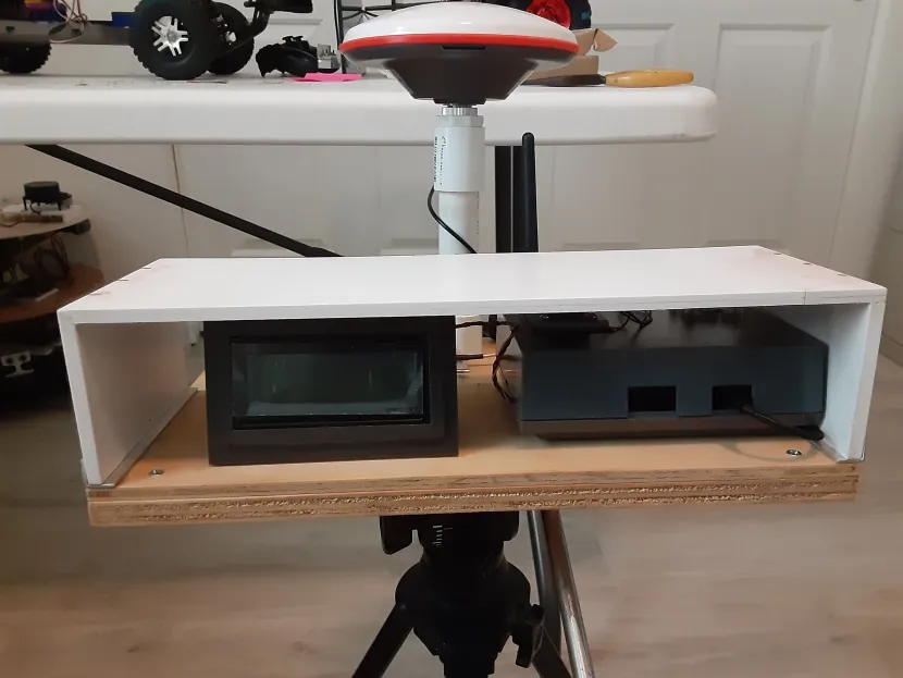
Below is a shot of my completed Base Station sitting on a camera tripod. The PVC mount for the Survey Grade L1/L2/L5 antenna can be seen in the back of the Base Station along with the Sik telemetry radio antenna.
Moving on to the Rover side of the Base Station/Rover setup, will require an additional Sparkfun ZED-F9P module, or equivalent, an appropriate L1/L2 band antenna, connecting cables, ground plane for the antenna, and the second Sik telemetry radio. Find appropriate mounting points on your RC Car for the GPS module, antenna, and Sik telemetry radio. I attached the second Sik telemetry radio to the Rover ZED-F9P module the same way that the Sparkfun “Setting up a Rover Base RTK System” attached the Sik telemetry radio to the Base Station ZED-F9P with the following exceptions: I used berg pin headers on the designated ZED-F9P UART2 pins and ran a jumper wire from a module unused 5 vdc pin hole to an unused pin hole where the UART2 pin holes were located, instead of soldering the Sik telemetry radio harness directly as in the tutorial, so I could build a wire harness connector for the Sik telemetry radio.
As far as Rover RTK GPS configurations go, I found the ArduSimple Rover 10Hz configuration file to work well with the Rover ZED-F9P though I kept the UART2 baud rate at 57600 and I removed all but the default GNRMC message from the USB output using the “Message” function in the U-Center Configuration view. However you are free to select whatever configuration suits your fancy.
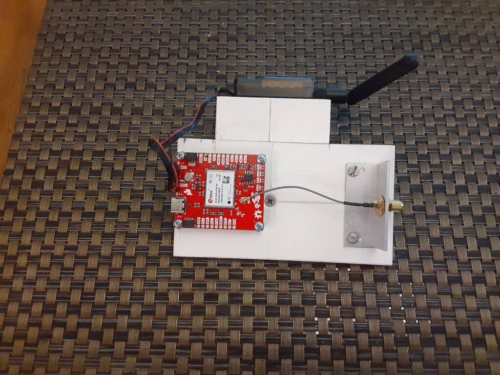
Here is a shot of my Rover ZED-F9P module and Sik telemetry radio sub-chassis that mounts on my Traxxas E-Maxx DC test vehicle. Not shown is the U-Blox L1/L2 band antenna that connects to the female SMA chassis connector at the back of the sub-chassis.
To ensure that the Base Station and the Rover are communicating correctly once the hardware has been built and configured, perform the following:
Setup the Base Station outside with a clear view of the sky and turn it on.
Bring the Rover outside and power up the SBC to provide power to ZED-F9P connected to a USB port.
The Rover ZED-F9P PPS LED should begin flashing after the cold start and the RTK LED should be a solid yellow indicating no “Float” or “Fix” solution.
After the Base Station LCD Display indicates that the Base Station has completed the survey-in mode and is transmitting RTCM messages, the Rover ZED-F9P RTK LED should start flashing indicating a RTK “Float” solution (<500 mm) and then go out completely indicating a RTK “Fix” solution (<14 mm).
Getting back to Donkey Car now that the RTK GPS Base Station and Rover hardware are functioning correctly, the Path Follow Autopilot (using GPS, wheel encoders, etc) guide can be found here. The Train a path follow autopilot link will get you going by providing detailed instructions for configuring your myconfig.py file and recording and playing back a recorded path.