Almost three years ago zlite contributed a blog post titled “Using ArduRover with an RTK GPS“. It was an excellent article that detailed using existing RTK GPS hardware available at the time to provide RC Car course guidance using ArduRover with a Base Station/Rover RTK GPS configuration. In this blog post I will detail how to use the Donkey Car Path_Follow template with RTK GPS hardware.
The Donkey Car Path_Follow template can be configured to use either wheel encoders or GPS to record a path and then have the RC Car autonomously track the recorded path from beginning to finish. For those of you who are not familiar with Donkey Car, the official website with instructions on how to build, configure, drive and then train a RC Car using either the Raspberry Pi or NVIDIA Nano 4GB Single Board Computers (SBC) can be viewed here. This article assumes that the user has already built their RC Car, programmed the selected SBC with an appropriate Operating System (OS), the Donkey Car app, created the car application using the path_follow template and is ready to procure, install, and program the necessary RTK GPS hardware.
There are presently two solutions to using RTK GPS hardware with the path_follow template car application with one being less expensive than the other. Both solutions require a Rover RTK GPS module and an appropriate antenna for the car, but then deviate as to from where the required course corrections for the Rover are received. The more expensive approach requires either the purchase or construction of a RTK GPS Base Station while the cheaper solution uses Internet-based corrections instead of a local base. A detailed tutorial, by Donkey Car Maintainer Ezward, on using the Internet-based corrections solution can be found here, while the rest of this blog post will be devoted to describing either purchasing or building a suitable RTK GPS Base Station, a telemetry system to communicate with the Rover, and the Rover RTK GPS module/antenna.
For those users with deep pockets, a ready built RTK GPS Base Station can be procured from Sparkfun.com here. For those of you who like to roll your own to build a Base Station, as I did, here are the steps I took to build a Base Station which assumes you know how to use the U-Blox U-Center, are proficient with the Arduino IDE, and have good soldering skills.
For a start, here is a list of the required hardware for the Base Station that I built:
- Sparkfun ZED-F9P RTK GPS module
- Sparkfun Thing Plus – ESP32 WROOM (USB-C) module
- Sparkfun 20 x 4 SerLCD display module
- Sparkfun GNSS Multi-Band L1/L2/L5 Surveying Antenna
- SiK Telemetry Radio V3 pair
- Sparkfun Reinforced Interface Cable
- Sparkfun Antenna Thread Adapter
- Sparkfun Qwiic Cable Kit Hook Up I2C
- Appropriate housings for the LCD Display and the GPS/WROOM modules
- Misc USB A to USB C cables for programming the ZED-F9P and ESP32 WROOM modules
- A suitable portable 5 vdc power supply: ie Anker Power Core 13000 Power Bank
Before moving ahead with the construction of the Base Station, you might want to familiarize yourself with the following tutorials:
- GPS-RTK2 Hookup Guide
- Setting up a Rover Base RTK System
- Sik Telemetry Radio
- ESP32 Thing Plus (USB-C) Hookup Guide
To configure the Base Station Sparkfun ZED-F9P RTK GPS module I followed the detailed steps in the Sparkfun “Setting up a Rover Base RTK System” tutorial with the following exceptions:
- I did not complete the initiation of the survey-in mode section of the tutorial because the ZED-F9P will not go into the survey-in mode from a cold start.
- I did not attach the first Sik telemetry radio to the ZED-F9P because I wanted to power the telemetry radio with 5 vdc which is not available on the Qwiic interconnection bus.
- See below how I programmed the Sparkfun Thing Plus to put the ZED-F9P into the survey-in mode from a cold start.
How to put the ZED-F9P into the survey-in mode from a cold start:
- Down load the Sparkfun Example4_BaseWithLCD.ino
- Follow the Sparkfun ESP32 Thing Plus (USB-C) Hookup Guide to program the Thing Plus with the Example4 .ino code which has bee updated since I worked with it.
a) A “delay(5000)” code has been removed from the lcd.print statements which means messages will just flash by on the LCD display. - I made the following changes to the Example4 .ino code:
a) I changed the code at line 52 to Serial1.begin(57600) to let the ESP32 Thing Plus Serial1 port transmit the RTCM correction messages.
b) I commented out the code at lines 81 and 82 because I am using the ESP32 Thing Plus Serial1 to transmit the RTCM correction messages over the telemetry link.
c) I commented out the following section of code: line 85 to line 105 because those CFG values were previously configured during the “Setting up a Rover Base RTK System” tutorial.
d) At line 129 I changed the 60 sec and 5.0 m to 600 sec and 1.0 m and usually get a position accuracy of under 0.7 m after 600 sec on a clear day.
e) I removed line 206 and replaced the code beginning at line 216 with the following code to allow the ESP32 Thing Plus Serial1 to transmit the RTCM messages over the telemetry link :
#ifdef USE_SERIAL1
//Push the RTCM data to Serial1
Serial1.write(incoming);
#endif
//Pretty-print the HEX values to Serial
if (myGNSS.rtcmFrameCounter % 16 == 0) Serial.println();
Serial.print(F(” “));
if (incoming < 0x10) Serial.print(F(“0”));
Serial.print(incoming, HEX);
}
To wire the Sik telemetry radio to the Sparkfun ESP32 Thing Plus I put individual female pins on the telemetry radio power, ground, tx, and rx pins and connected them to the appropriate berg header pins soldered to the ESP32 Thing Plus pwb at TX, RX, GND, and FREE. I soldered a jumper wire from FREE to V_USB to provide 5 vdc to the telemetry radio.
I then connected the ESP32 Thing Plus to the ZED-F9P and the LCD Display using the Qwiic bus cables from the parts list. Powering the ESP32 Thing Plus USB C connector from the 5 vdc Power Bank provides 3.3 vdc power to the ZED-F9P and the LCD Display over the Qwiic bus and starts the ZED-F9P in the survey-in mode.
When 5 vdc power is applied to the ESP32 Thing Plus USB C connector, the LCD Display will display “LCD Ready” followed by “GNSS Detected” indicating that the modules connected over the Qwiic bus are operational and functioning correctly. The ESP32 Thing Plus will then put the ZED-F9P in the “survey-in” mode then display “Survey in progress” at the top of the LCD Display followed by “Elapsed: ” and “Accuracy: ” on individual lines below. The “Elapsed” time will count upwards to whatever survey time you have selected and the Accuracy” position will count downwards towards whatever survey accuracy you have chosen. The survey-in mode will terminate when both (and) the survey time and survey accuracy values selected are met. The LCD Display will then display “Transmitting RTCM” and the Sik telemetry radio red transmit LED will begin to flash at a 1Hz rate indicating the telemetry transmission of RTCM correction messages.
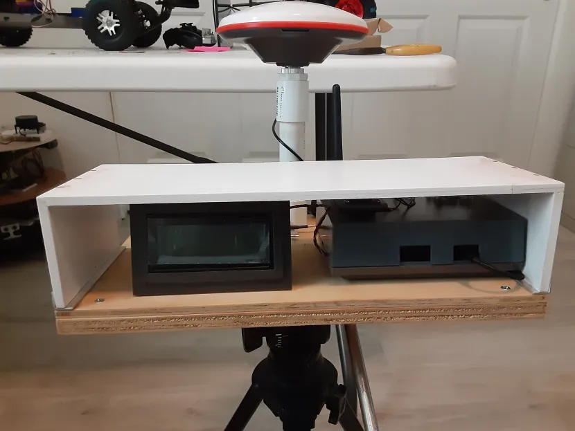
Below is a shot of my completed Base Station sitting on a camera tripod. The PVC mount for the Survey Grade L1/L2/L5 antenna can be seen in the back of the Base Station along with the Sik telemetry radio antenna.
Moving on to the Rover side of the Base Station/Rover setup, will require an additional Sparkfun ZED-F9P module, or equivalent, an appropriate L1/L2 band antenna, connecting cables, ground plane for the antenna, and the second Sik telemetry radio. Find appropriate mounting points on your RC Car for the GPS module, antenna, and Sik telemetry radio. I attached the second Sik telemetry radio to the Rover ZED-F9P module the same way that the Sparkfun “Setting up a Rover Base RTK System” attached the Sik telemetry radio to the Base Station ZED-F9P with the following exceptions: I used berg pin headers on the designated ZED-F9P UART2 pins and ran a jumper wire from a module unused 5 vdc pin hole to an unused pin hole where the UART2 pin holes were located, instead of soldering the Sik telemetry radio harness directly as in the tutorial, so I could build a wire harness connector for the Sik telemetry radio.
As far as Rover RTK GPS configurations go, I found the ArduSimple Rover 10Hz configuration file to work well with the Rover ZED-F9P though I kept the UART2 baud rate at 57600 and I removed all but the default GNRMC message from the USB output using the “Message” function in the U-Center Configuration view. However you are free to select whatever configuration suits your fancy.
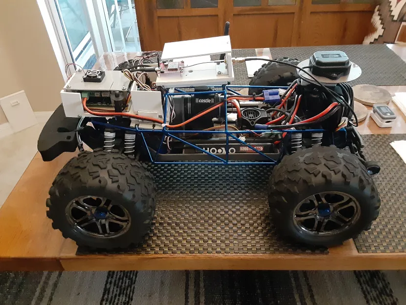
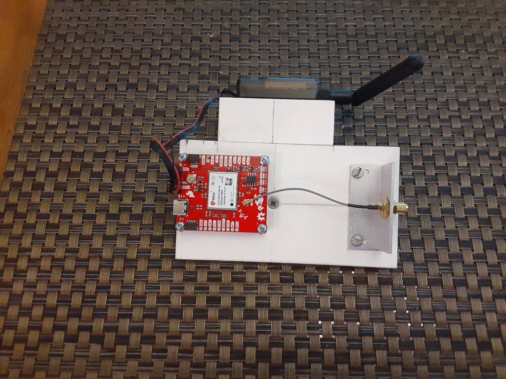
Here is a shot of my Rover ZED-F9P module and Sik telemetry radio sub-chassis that mounts on my Traxxas E-Maxx DC test vehicle. Not shown is the U-Blox L1/L2 band antenna that connects to the female SMA chassis connector at the back of the sub-chassis.
To ensure that the Base Station and the Rover are communicating correctly once the hardware has been built and configured, perform the following:
- Setup the Base Station outside with a clear view of the sky and turn it on.
- Bring the Rover outside and power up the SBC to provide power to ZED-F9P connected to a USB port.
- The Rover ZED-F9P PPS LED should begin flashing after the cold start and the RTK LED should be a solid yellow indicating no “Float” or “Fix” solution.
- After the Base Station LCD Display indicates that the Base Station has completed the survey-in mode and is transmitting RTCM messages, the Rover ZED-F9P RTK LED should start flashing indicating a RTK “Float” solution (<500 mm) and then go out completely indicating a RTK “Fix” solution (<14 mm).
Getting back to Donkey Car now that the RTK GPS Base Station and Rover hardware are functioning correctly, the Path Follow Autopilot (using GPS, wheel encoders, etc) guide can be found here. The Train a path follow autopilot link will get you going by providing detailed instructions for configuring your myconfig.py file and recording and playing back a recorded path.