As we integrate depth sensing more into the DIY Robocars leagues, I’ve been using a simple maze as a way to test and refine various sensor and sensor processing techniques. In my last maze-navigating post, I used a Intel RealSense depth camera to navigate my maze. In this one, I’m using a low-cost 2D Lidar, the $99 YDlidar X4, which is very similar to the RPLidar A1M8 (same price, similar performance). This post will show you how to use it and walk through some lessons learned. (Note: this is not a full tutorial, since my setup is pretty unusual. It will, however, help you with common motion control, Lidar threading and motion planning problems.)
First, needless to say, Lidar works great for this task. Maze following with simple walls like my setup is a pretty easy task, and there are many ways to solve it. But the purpose of this exercise was to set up some more complex robotics building blocks that often trip folks up, so I’ll drill down on some of the non-obvious things that took me a while to work out.
Hardware
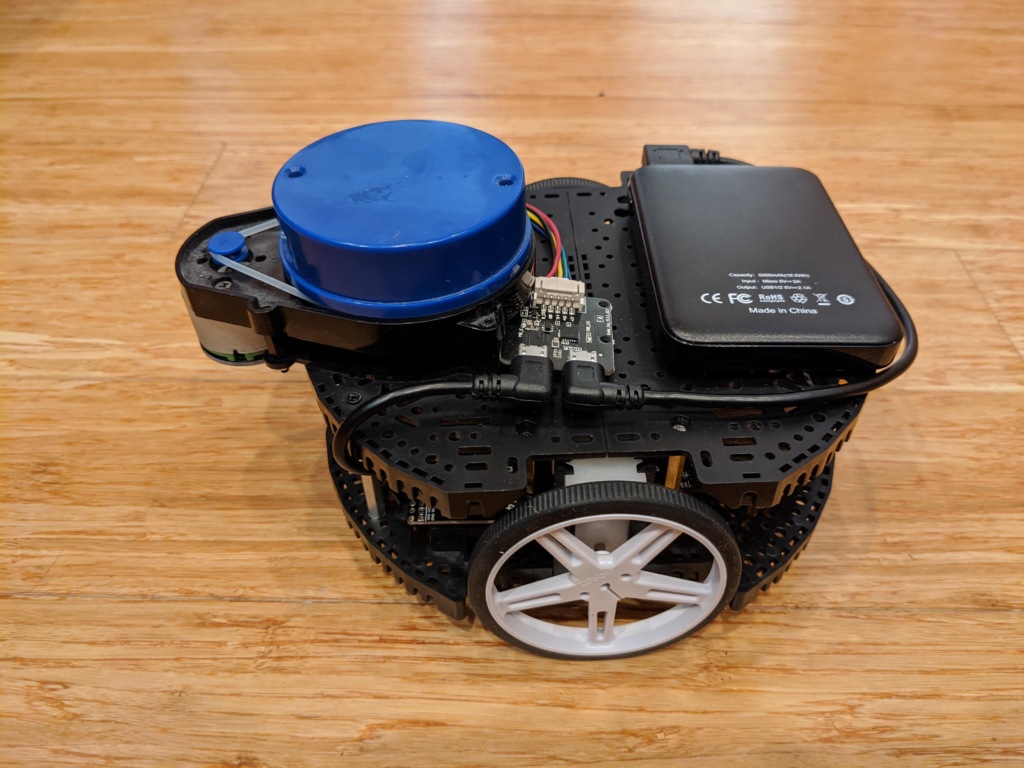
First, my setup: I used a Pololu Romi chassis with motor encoders and a Romi32U control board. Two expansion plates on the top provide a surface for the Lidar. The 32U control board mounts a RaspberryPi 3, which is what we’ll use for most of the processing. Just mount the Lidar on the top, as I have in the picture above, and power it with a separate USB battery (any cheap phone charging battery will work) since the RaspberryPi USB port won’t provide enough power.
Software
The below is a description of some hard things I had to figure out, but if you just want to go straight to the Python code, it’s here.
1) Closed-loop motor control. Although there are lots of rover chassis with perfectly good motors, I’m a bit of a stickler for closed-loop motor control using encoders. That way you can ensure that a rover goes where you tell it to, even with motors that don’t perform exactly alike. This is always a hassle to set up on a new platform, with all sorts of odometry and PID loop tuning to get right. Ideally, the Romi should be perfect for this because it has encoders and a control board (which runs an Arduino-like microprocessor) to read them. But although Pololu has done a pretty good job with its drivers, it hasn’t really provide a complete closed-loop driving solution that works with Python on the on-board RaspberryPi.
Fortunately, I found the RomiPi library that adds proper motion control to the Romi, so if you say turn 10 degrees to the left it actually does that and when you say go straight it’s actually straight. Although it’s designed to work with ROS, the basic frameworks works fine with any Python program. There is one program that you load on the Romi’s Arduino low-level motor controller board and then a Python library that you use on the RaspberryPi. The examples show you how to use it. (One hassle I had to overcome is that it was written for Python 2 and everything else I use needs Python 3, but I ported it to Python 3 and submitted a pull request to incorporate those changes, which was accepted, so if you download it now it will work fine with Python 3)
2) Multitasking with Lidar reading. Reading the YDLidar in Python is pretty easy, thanks to the excellent open source PyLidar3 library. However, you’ll find that your Python code pauses every time the library polls the sensor, which means that your rover’s movements will be jerky. I tried a number of ways to thread or multitask the Lidar and the motor parts of my code, including Asyncio and Multiprocessing, but in the end the only thing that worked properly for me was Python’s native Threading, which you can see demonstrated in PyLidar3’s plotting example.
In short, it’s incredibly easy:
Just import threading at the top of your Python program:
import threadingAnd then call your motor control routine (mine is called “drive”) like this:
threading.Thread(target=drive).start()3) Sampling strategies. I totally overthought this one. I tried all sorts of things, from trying to average all the distance points in the Lidar’s 360 degree arc to just trying to find the longest free distance and heading in that way. All too noisy.
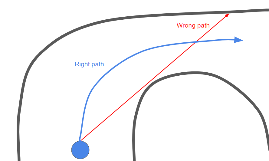
I tried batching groups of ten degrees and doing it that way: still too noisy, with all sorts of edge cases throughout the maze. The problem is that you don’t actually want to steer towards the longest free path, because that means that you’ll hit the edge of the corner right next to the longest free path, like this:
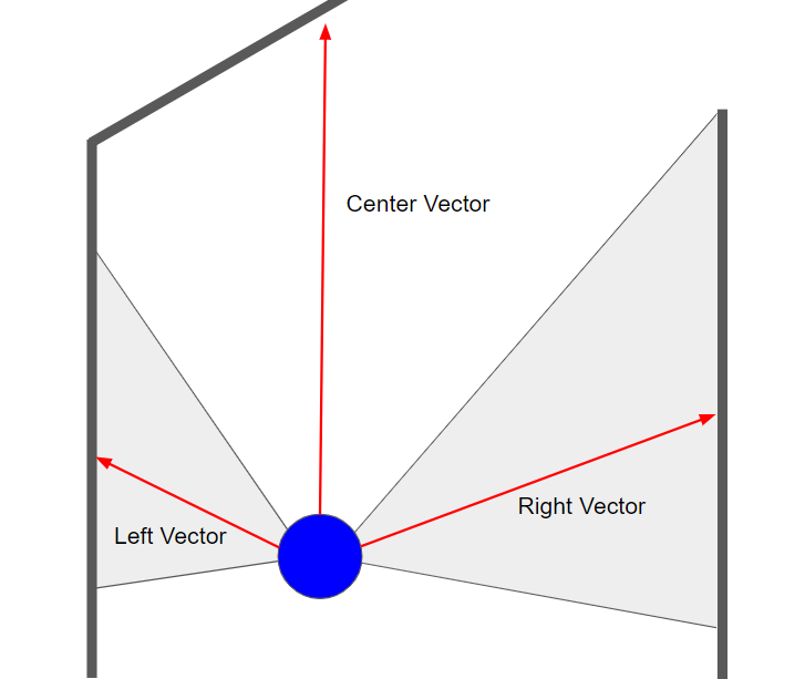
Instead, the best strategy turned out to just keep it simple: define a left side (say 20 to 100 degrees, if straight ahead is 0 degrees), a right side (260 to 340 degrees) and a center (340 to 20 degrees). Get an average distance (vector) for each, like this:
Now that you have three vectors, you can sum them and get the net vector like this (I halve the center vector because avoiding the walls to right and left is more important than seeking some distant free space):
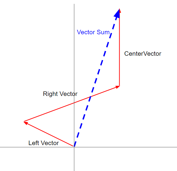
If you set the right and left angles to 45 degrees (pi/4 in radians, which is what Python uses), you can decompose the x and y average values of each zone and add them together like this:
        left_y = math.sin(math.pi/4) * left_average
        left_x = -1*math.cos(math.pi/4) * left_average
        right_y = math.sin(math.pi/4) * right_average
        right_x = math.cos(math.pi/4) * right_average
        center_y = center_average

        sum_x = round(left_x + right_x,2)
        sum_y = round(center_y - (left_y + right_y)/2,2)
        if sum_y < 100:
            sum_y = 100
        sum_angle = math.atan2(sum_x,sum_y)
That’s pretty much it. It seems so simple now, but all these things took days to figure out. Hope this guide will help save you some of that time!