Even though RTK GPS hardware has come down in price substantially over the last couple of years, building a RTK GPS Base Station is still not inexpensive for the average RC Car enthusiast. However there is hope and I will show how a barebones Base Station can be built at a reasonable out of pocket cost.
The cost of the Base Station I described and built in my recent Blog post Using the Donkey Car Path_Follow Template with RTK GPS pencils out to around $580 (plus shipping for some of the parts) which puts it over $600. This barebones Base Station can be built for under $400. Interested? Then read on.
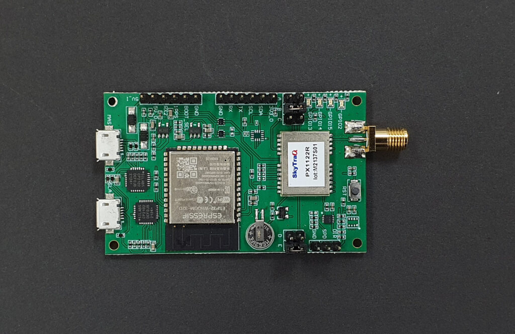
The Barebones Base Station, unlike my original Base Station, integrates the RTK GPS module with the ESP32 WROOM processor and does away with the LCD Display, but retains the Sparkfun L1/L2/L5 Survey Grade antenna (for future proof operation) and the Sik telemetry radio for RTCM message transmission to the Rover. The integrated RTK GPS module/Processor (PX1122R L1/L2 RTK Evaluation Board shown above) comes from the NavSpark Store in Taiwan and can be found here on the store website. Before you get all excited about the low price of $95 compared to the Sparkfun ZED-F9P RTK GPS module, just remember that the module is being shipped from Taiwan by FedEx air which, in my case added $55 to the cost of the module as I live on the US East Coast, will probably run between $50-$60 depending on where you live. Obviously the closer to Taiwan that you live, the cheaper the FedEx shipping will be. I queried the NavSpark Store as to a possible US distributor, but it was a no-go as they said that the overhead was too high to make a reasonable profit. Bummer to say the least.
Before moving on to the programming and evaluation of the PX1122R L1/L2 RTK Evaluation Board, a word about the Sparkfun L1/L2/L5 Survey Grade antenna. The L5 band upgrade is preoperational and should be fully in place by 2027 so the Sparkfun antenna should future proof your Base Station as RTK GPS modules that support the L1/L2/L5 bands become available. However there is a cheaper L1/L2 Survey Grade antenna that can be found here for $78. I have tested this Beitian BT-160 on a NavSpark Store PX1122R Breakout Board and it provided performance comparable to the Sparkfun Survey Grade antenna for about $50 less.
The programming of the PX1122R L1/L2 RTK Evaluation Board can be accomplished by following the steps in the Getting Started with PX1122R RTK Evaluation Board to install the Windows GNSS Viewer on page 3 and for setting up the EVB as a Base Station (2/3) using the Survey Mode on page 10. Based on my experience with the Sparkfun ZED-F9P using the survey-in mode, I recommend a Survey Time of 600 (sec) and a Standard Deviation value of 30 (cm) though other users seem to like the default values of a Survey Time of 60 (sec) and a Standard Deviation value of 30 (cm).
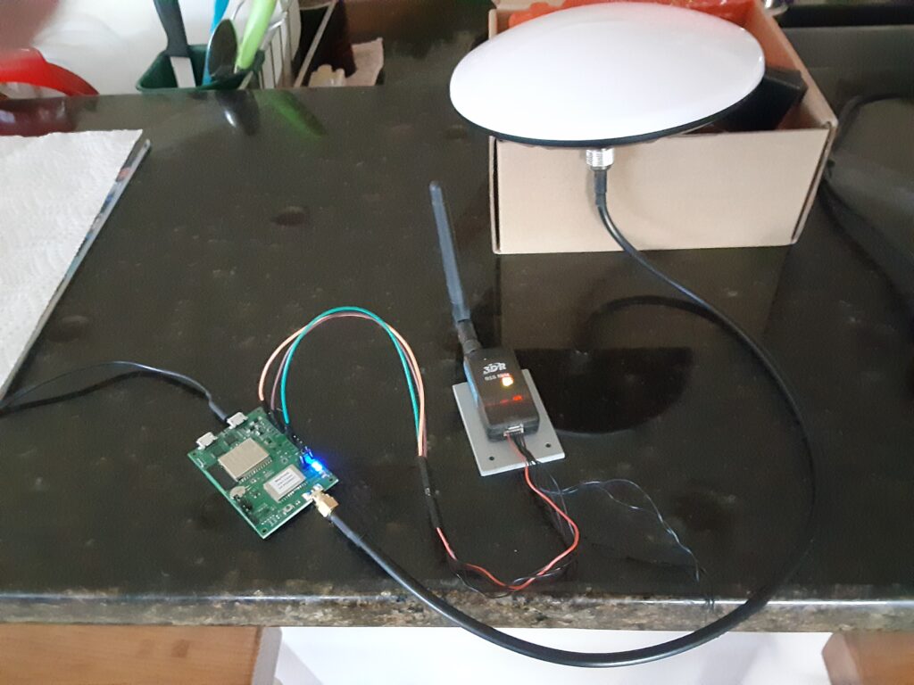
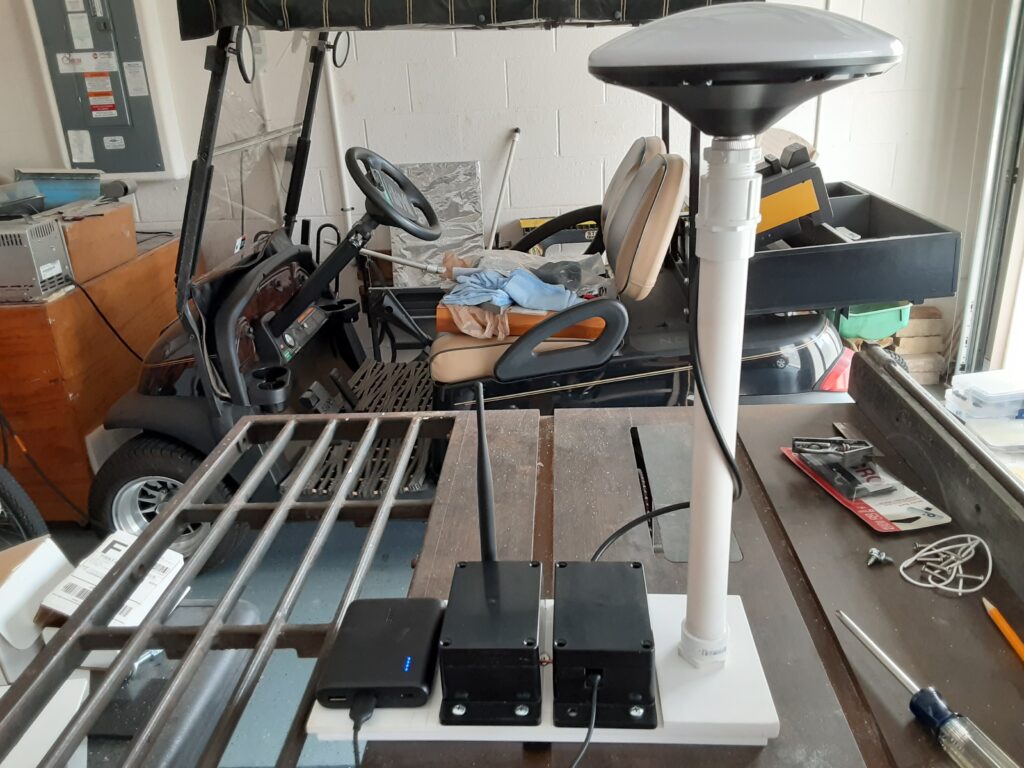
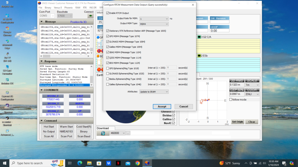
Now is the time to select a suitable enclosure for the Evaluation Board (EVB) and attach the Sik telemetry Radio and suitable Survey Grade Antenna as seen without an enclosure in my prototype photo below and the completed Base Station in the second photo below. The Very Quick Short Baseline Test (1/2) on page 13 can be used to determine the location of the TX, GND, and 5V_O pins on the EVB that should be connected to the Sik telemetry radio to transmit the RTCM correction messages to the Rover. The EVB TX pin should be connected to the RX (2) on the Sik telemetry radio while the GND and 5V_O connect to the Sik telemetry radio Ground (6) and the Power (1) respectively. The EVB TX pin must be set to 57,600 baud as shown in the third photo below. Unfortunately the NavSpark Store designers did not use a separate UART to transmit RTCM correction messages, like Sparkfun does, so the USB1 and the TX/RX UART must be the same rate of 56,700 baud. This should not create a problem since the RTCM correction messages being output on USB1 are for observation only with the GNSS Viewer therefore speed is not an issue. The only item left now is to verify the RTCM correction message output. This can be accomplished by clicking on the GNSS Viewer RAW tab and selecting “Configure RTCM Measurement Data Out” as shown in the fourth photo below. Since the “RTCM Measurement Data Out” default configuration was very similar to the Sparkfun recommended configuration for the ZED-F9P Base Station, I left them as is. If you decide to make changes to the “RTCM Measurement Data Out” default configuration, make sure you select “Update to SRAM+Flash and then hit the “Accept” button.
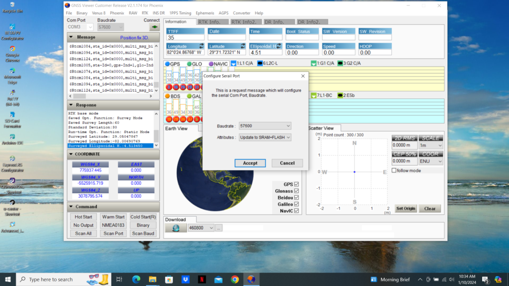
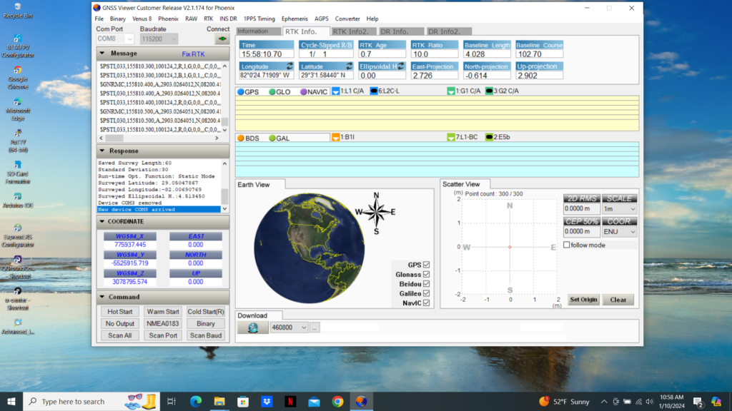
Now comes the proof of the pudding so to speak. I started up the PX1122R L1/L2 RTK Breakout Board located on my DC Lawnmower Rover by plugging the Breakout Board Sparkfun UART to USB converter output to my trusty laptop running the GNSS Viewer. I then plugged the Base Station Evaluation Board USB1 output into a suitable 5 vdc supply and watched the PX1122R L1/L2 RTK Breakout Board GNSS Viewer output shift from “Position fix 2D” in the Message Bar to “Float RTK” and finally to “Fix RTK” (see photo below) once the Base Station Evaluation Board has completed its Survey Mode and began transmitting RTCM correction messages to the Rover Breakout Board. If you are using a Sparkfun ZED-F9P RTK GPS module on your Rover, you should see the module RTK yellow LED go from solid yellow to flashing yellow (Float) and finally go out completely (Fix) once the Base Station has completed the Survey Mode and a Fix solution is reached.
Questions or comments? Please post below.
Hi. I have two px 1122r i want to set as base and rover correction via radio. I have 2w uhf radio. What is the best configuration for this setup?