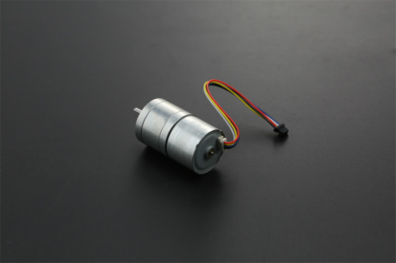
DF Robot has an interesting new robotics motor ($19), which has both the motor controller and the encoder integrated into the body. That means that you can drive it straight from an Arduino, with no separate motor controller required. That’s pretty cool and leads the way to very simple rover setups.
The motor is 12v (good choice for a 3-cell, 11.1v lipo battery), geared to max 159 rpm. It’s smaller than the usual robot motors, but has enough power for a small rover.
Because it’s so well integrated with controller and encoder, it’s a good way to demonstrate proper PID motor control. So here’s a demo! The code is here:
Connect it to an Arduino like this (the wire colors will probably be different; pay them no mind. Just keep the red and black right and connect the others in the following order). Important: you must also connect the Arduino ground to the 12v power supply ground as shown):
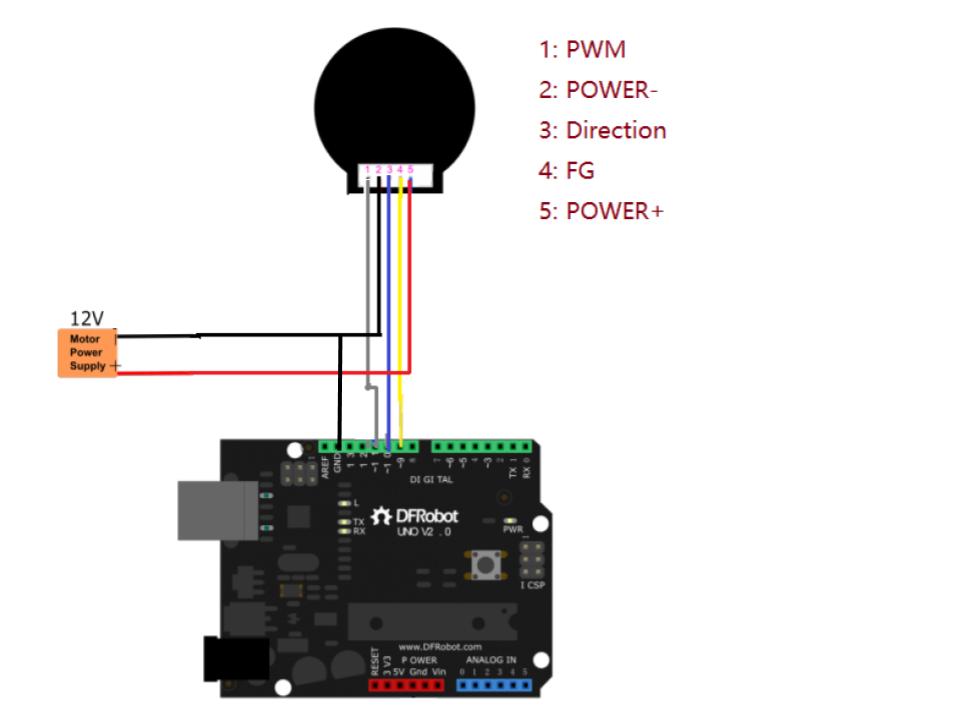
Full details are in the DF Robot wiki
Now try it with a PID controller, which will maintain a desired RPM within a reasonable range (80-140 rpm). Here’s some Arduino code that will do that.
Try playing around with the Kp (proportional), Ki (integral) and Kd (derivative) terms in this code and see what happens when you enter a different speed (80, 100, 120, etc). With the stock settings below, the Ki term will slowly build up so the RPMs approach the desired speed. A higher Kp term will speed up that convergence, but too high will overshoot. Here’s a short video that gives the basics, but the key points is that it uses feedback.
You want the speed of the motor to be a certain value, but just commanding it to go to a certain power doesn’t mean that it will get to exactly the desired speed (because of variation in battery voltage, etc). So rather than just sending a command and hoping for the best, you measure the actual speed the motor is turning with the encoder. Then just keep changing the motor control inputs until the motor speed output is close to the desired one — that’s what a PID controller does. All the various settings (P. I. D.) are just to tune it so it does that well.
// Make sure you've added the official Arduino PID library to your libraries
// https://playground.arduino.cc/Code/PIDLibrary/
include
int i = 0;
int rpm;
unsigned long time = 0;
bool direction = HIGH;
int speed;
double Setpoint, Input, Output; // Setpoint is going to be the desired speed. Input will be encoder reading. Output will be motor command
double Kp = 0.5;
double Ki = 3;
double Kd = 0;
//Specify the links and initial tuning parameters
PID myPID(&Input, &Output, &Setpoint,Kp,Ki,Kd, REVERSE);
void setup() {
Serial.begin(115200);
pinMode(10, OUTPUT); //PWM PIN 10 with PWM wire
pinMode(11, OUTPUT);//direction control PIN 11 with direction wire
digitalWrite(10, direction);
Setpoint = 100;
Input = 100;
myPID.SetMode(AUTOMATIC);
}
void loop() {
if (Serial.available()) {
speed = Serial.parseInt();
speed = 255 - speed;
delay(200);
}
for(int j = 0;j<8;j++) { i += pulseIn(9, HIGH, 500000); //SIGNAL OUTPUT PIN 9 with white line,cycle = 2i,1s = 1000000us,Signal cycle pulse number:272 } i = i >> 3;
rpm = 111111 / i; //speed r/min (601000000/(4562i))
i = 0;
// Serial.print(rpm);
// Serial.println(" r/min");
Setpoint = 255-speed;
Input = rpm;
myPID.Compute(); // calculate the right motor control to make rpm equal desired speed
if (Output > 220) {Output = 220;}
if (Output < 20) {Output = 20;}
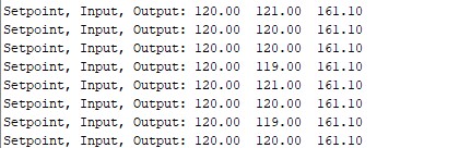
Serial.print("Setpoint, Input, Output: ");
Serial.print(Setpoint);
Serial.print(" ");
Serial.print(Input);
Serial.print(" ");
Serial.println(Output);
analogWrite(11, Output);
}
If you enter a desired RPM between 80 and 130 in the Arduino Serial Terminal it will try to hit that number. Output should look something like this (“Setpoint” is PID-talk for “desired speed”. “Input” is the reported speed from the motor encoder. “Output” is the motor control signal [0-255] that the code sends the motor):