For reasons that probably involve too much starting projects and not enough thinking about why I was starting them, I have conducted an experiment in comparing an array of ultrasonic sensors with an array of time-of-flight Lidar sensors. This post will show how to make both of them as well as their pros and cons. But [spoiler alert] at risk of losing all my readers in the first paragraph, I must reveal the result: neither are as good as a $69 2D Lidar.
Nevertheless! If you’re interested in either kind of sensors, read on. There are some good tips and lessons below.
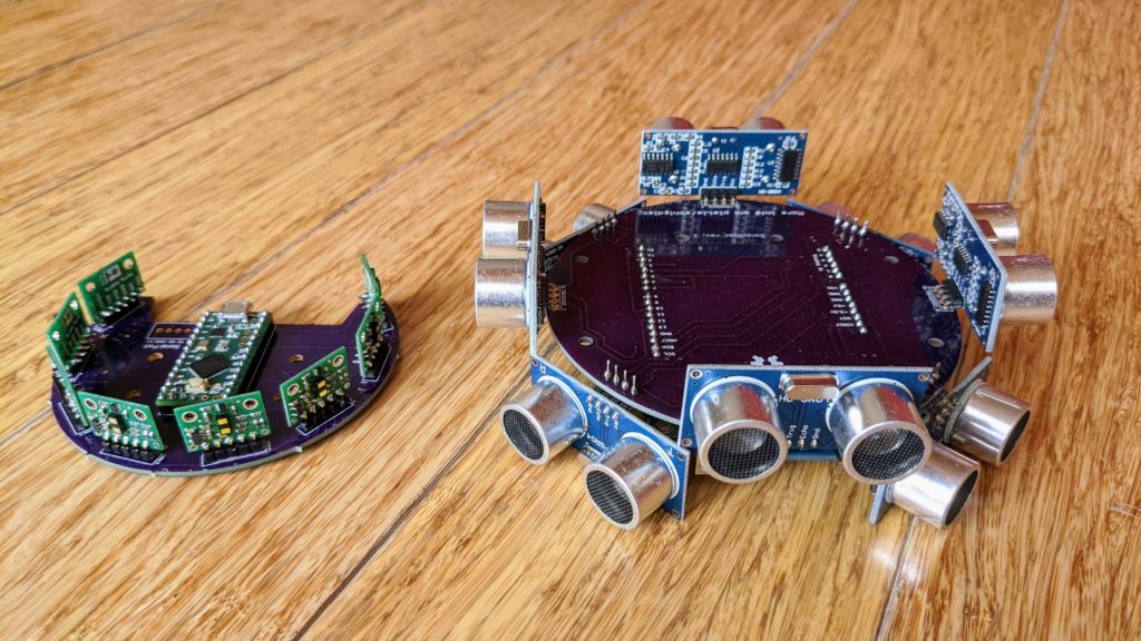
First, how this started. My inspiration was the SonicDisc project a few years ago from Dimitris Platis, which arranges eight cheap ultrasonic sensors in a disc and makes it easy to read and combine the data.
I ordered the PCBs and parts that Dimitis recommended, but got busy with other things and didn’t get around to assembling them until this year. Although I eventually did get it working, it was kind of a hassle to solder together an Arduino from the basic components, so I redesigned the board to be an Arduino shield, so it just plugs on top of a regular Arduino Uno or the like. If you want to make one like that, you can order my boards from OSH Park here. The only other parts you’ll need are eight ultrasonic sensors, which are very cheap (just $1.40 each). I modified Dimitris’ Arduino code to work as an Arduino shield; you can get my code here.
Things to note about the code: It’s scanning way faster (~1000hz) than needed and fires all the ultrasonic sensors at the same time, which can lead to crosstalk and noise. A better way would be to fire them one at a time, at the cost of some speed. But anything faster than about 50-100Hz is unnecessary since we can’t actuate a rover faster than about 10hz. Any extra scan data can be used for filtering and averaging. You’ll note that it’s also set-up to be able to send the data to another microprocessor via I2C if desired.
While I was making that, I started playing with the latest ST time-of-flight (ToF) sensors, which are like little 1D (just a single fixed beam) Lidar sensors. The newest ones, the VL53L1X, have a range of up to 4m indoors and are available in an easy-to-use breakout board form from Pololu ($11 each) or for a bit more money but a better horizontal configuration of the sensor, from Pimoroni ($19 each).
The advantage of the ToF sensors over ultrasound is that they’re smaller and have a more focused, adjustable beam, so they should be more accurate. I designed a board that used an array of eight of those with an onboard Teensy LC microprocessor (it works like an Arduino, but it’s faster and just $11). You can buy that board from OSH Park here. My code to run it is here, and you’ll need to install the Pololu VL53L1X library, too.
The disadvantage of the ToF sensors is that they’re more expensive, so an array of 8 plus a Teensy and the PCB will set you back $111, which is more expensive than a good 2D Lidar like the RPLidar A1M8, which has much higher resolution and range. So really the only reason to use something like this is if you don’t want to have to use a Linux-based computer to read the data, like RPLidar requires, and want to run your car or other project entirely off the onboard Teensy. Or if you really don’t want any moving parts in your Lidar but need a wider field of view than most commercial solid-state 2.5D Lidars such as the Benewake series.
Things to note about the code: Unlike the ultrasonic sensors, the TOF sensors are I2C devices. Not only that, but the devices all come defaulting to the same I2C addresses, which it returns to at each power-on. So at the startup, the code has to put each device into a reset mode and then reassigns it a new I2C address so they all have different addresses. That requires the PCB to connect one digital pin from the Teensy to each sensor’s reset pin, so the Teensy can put them into reset mode one-by-one.
Once all the I2C devices have a unique ID, each can be triggered to start sampling and then read its data. To avoid cross-talk between them, I do that in three groups of 2-3 sensors each, with as much physical separation between them. Because of this need to not have them all sampling at the same time and the intrinsic sampling time required for each device, the whole polling process is a lot slower than I would like and I haven’t found a way to get faster than 7Hz polling for the entire array.
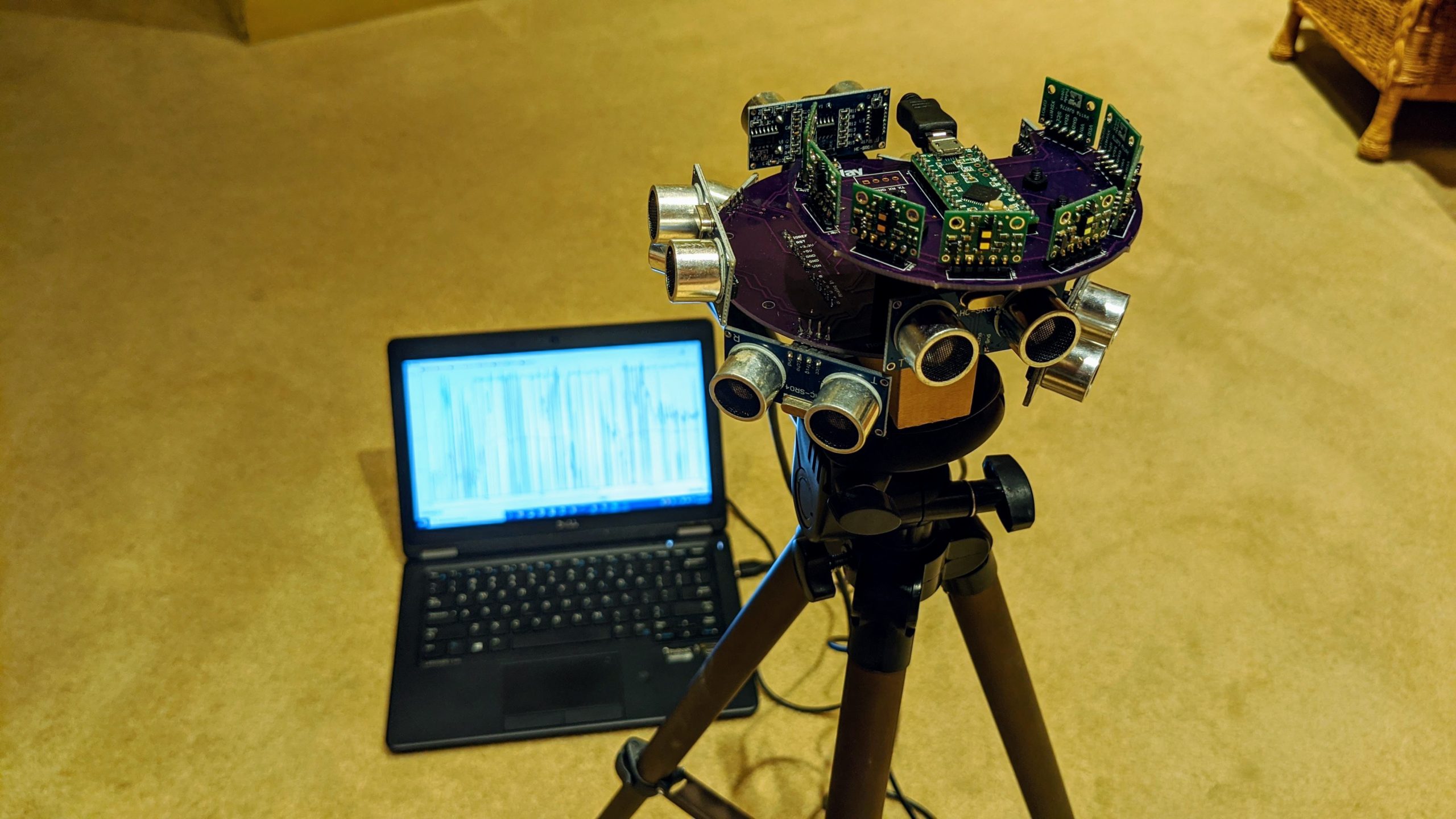
Testing the two arrays side by side, you can see some clear differences in the data below as I move a target (my head ;-)) towards and away from the arrays.
First, you can see that the ultrasonic array samples much faster, so one sequence of me moving my head closer and further takes up the whole screen, as it scrolls faster than the ToF lidar display below it, where I can do it dozens of times in the time it takes the data to scroll off the screen
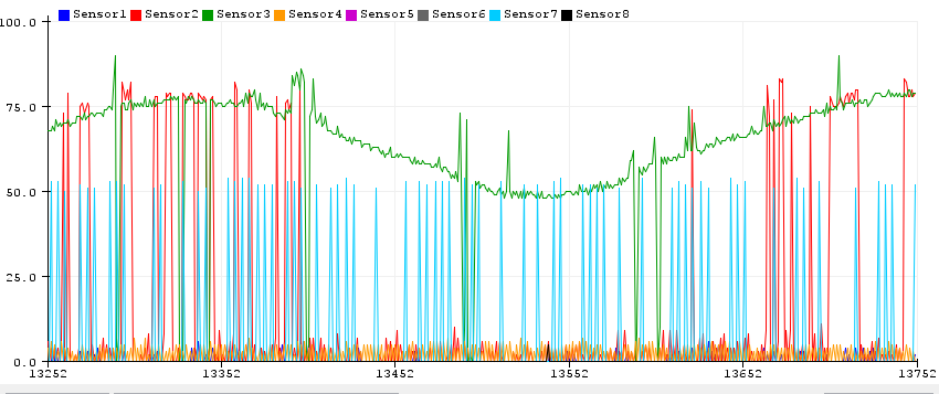
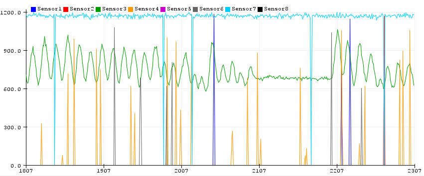
Second, you can see that the Sonar data is noisier. Most of the spurious readings in the ToF Lidar graph (ie, not the green line, which was the sensor pointed right at me) are from the sensor next to it (yellow), which makes sense since the sensors all have a beam spread that could have easily overlapped with the main sensor pointed at me.
That’s true for the sonar data, too (the red line is the sensor right next to the green line of the one pointed at me), but note how the green line, which should be constantly reporting my distance, quite often drops to zero. The blue line, which is a sensor on the other side of the array, is probably seeing a wall that isn’t moving that’s right at the limits of its range, which is why it drops in and out.
So what can we conclude from all this?
- ToF Lidar data is less noisy than sonar data
- ToF Lidar sensors are slower than sonar sensors
- ToF Lidar sensors are more expensive than sonar sensors
- Both ToF Lidar and Sonar 1D depth sensors in an array have worse resolution, range and accuracy than 2D Lidar sensors
- I’m not sure why I even tried this experiment, since 2D Lidars are great, cheap and easily available 😉
Is there any way to make such an array useful? Well, not the way I did it, unless you’re super keen not to use a 2D mechanical spinning lidar and a RaspberryPi or other Linux computer.
However, it is interesting to think about what a dense array of the ToF chips on a flexible PCB would allow. The chips themselves are about $5 each in volume, and you don’t need much supporting circuitry for power and I2C, most of which could be shared with all the sensors rather than repeated on each breakout board as in the case with the Pololus I used. Rather than have a dedicated digital pin for each sensor to put them in reset mode to change their address, you can use an interrupt-driven daisy-chain approach with a single pin, as FuzzyStudio did. And OSHPark, which I use for my PCBs, does flex PCBs, too.
With all that in mind you could create a solid-state depth-sensing surface of any size and shape. Why you would want that I’m not sure, but if you do I hope you will find the preceding useful.