Whoa, wait a minute! Isn’t this a Robo Car website? True, but wouldn’t it be nice to have an autonomous lawnmower to save you from spending time mowing your lawn and therefore give you more free time to do RC Car racing? If so, read on to give you an idea of how I built my low budget prototype autonomous robotic lawnmower, but please remember this is just a guide and none of this design is set in stone.
Warning! This article describes the process of building an autonomous lawn mower for your entertainment and scientific inquiry. THIS IS NOT AN INSTRUCTION MANUAL OR GUIDE FOR BUILDING AUTONOMOUS MOWERS. IF YOU DECIDE TO BUILD ANYTHING YOU ARE DOING SO AT YOUR OWN RISK. A full size autonomous lawnmower, like this one, can be a VERY DANGEROUS machine — please consider carefully the implications before even thinking about building a machine like that. If you plan on building a self-driving mower you are doing so at your own risk.
Additionally, ArduPilot’s Developer Code of Conduct explicitly excludes ArduPilot from running systems where ArduPilot is effectively in control of human lives.
If you do a search on the IoT for “diy autonomous robotic lawnmowers” you will come across a vast selection of diy autonomous robotic lawnmower articles ranging from simple and inexpensive to very complex and very costly. Basically autonomous robotic lawnmowers have been around for quite a while and were kept within the lawn cutting area by sensing a wire buried around the perimeter of the cutting area of interest. However, now that GPS and especially RTK GPS guidance controllers have come into the hobbyist price range, building an autonomous robotic lawnmower using RTK GPS guidance has become a reality. Whereas the wire sensing autonomous robotic lawnmowers usually followed a random cutting pattern, sometimes cutting the same cutting area multiple times, the RTK GPS guided autonomous robotic lawnmowers can be programmed to meticulously cut a nonrepeating swath of grass row after row until the lawn is completely mowed. Still interested? Now on to the nuts and bolts of building an autonomous robotic lawnmower.
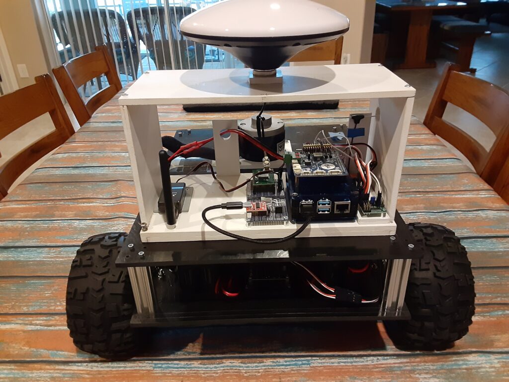
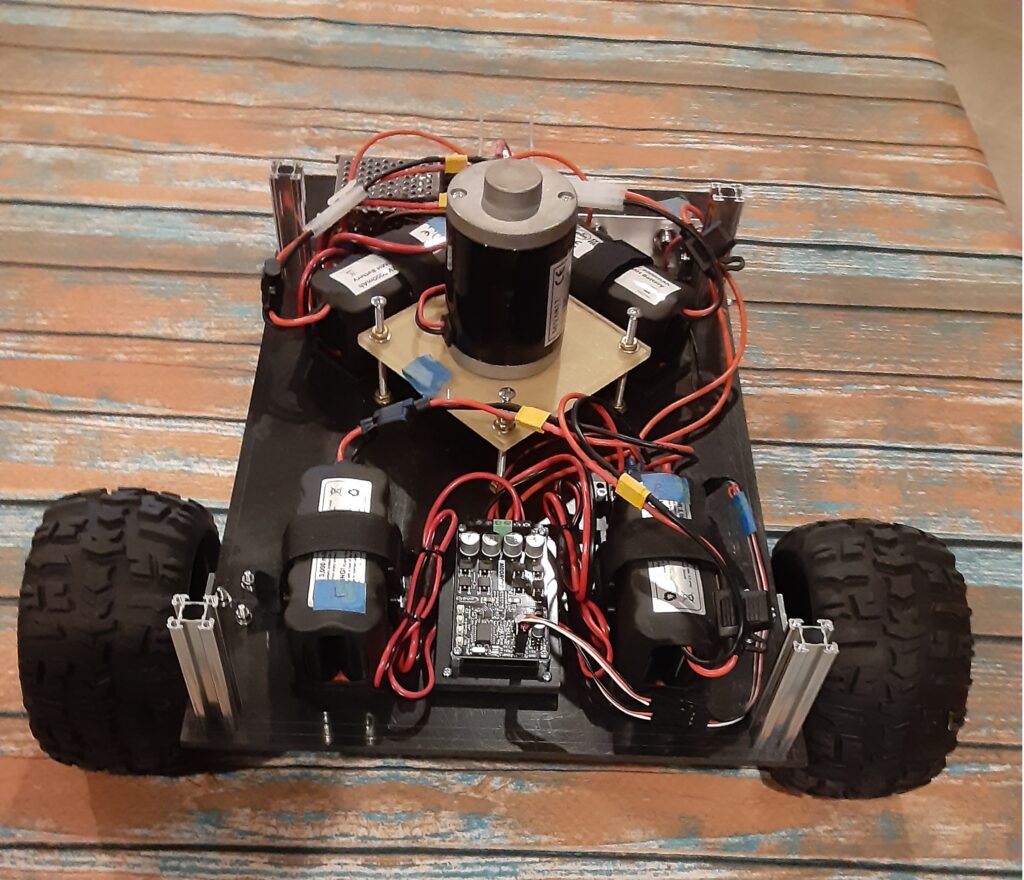
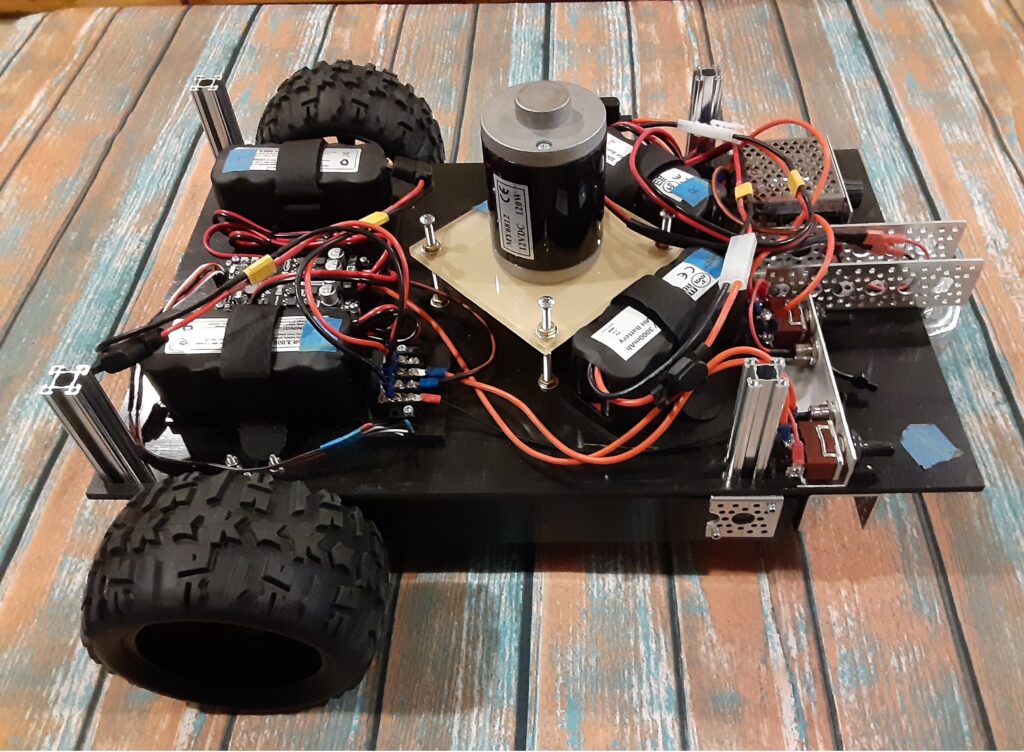
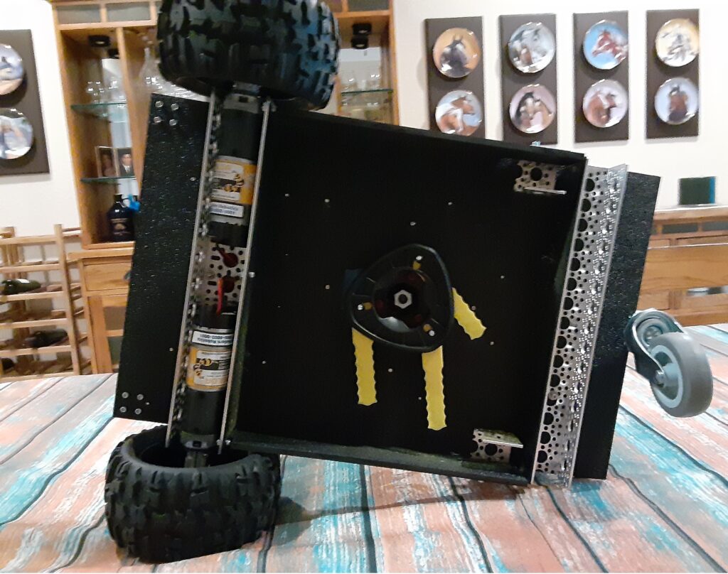
The typical autonomous robotic lawnmower is usually composed of a chassis, some form of motive power, a cutting head, a power source, and some form of cutting path guidance. I chose 1/4 inch thick black ABS plastic sheets to build the chassis which consists of two plates one 19 inches X 12 inches and the other smaller plate 15 inches X 12 inches. The larger plate serves as the mounting point for the differential steering motor controller, the drive motors, the cutting head motor, the batteries, the power switches, and a speed controller for the cutting head motor. The three photos below show how I positioned the aforementioned components on the main 19 inches X 12 inches plate. The smaller plate is attached to the main chassis plate with 72mm long 1109 Series goRAIL, one in each corner using appropriate metric hardware, to provide a mounting surface for the RTK GPS Path Guidance Module as shown in the fifth photo below.
The differential steering motor controller receives steering and throttle PWM signals from the RTK GPS Path Guidance Module and converts those PWM signals to differential steering and throttle voltages to control the two 12vdc drive motors.
The drive motors are mounted in U-channel with L-brackets, shown in the fourth photo below, and are coupled to two GLOBACT 1/8 1/10 17mm Hex RC Wheels and Tires using a D-shaft clamp, a 12mm Hex Wheel Adaptor, and finally a 12mm Hex to 17mm Hex Wheel Adaptor with appropriate metric machine screws. The rear caster wheel is 3 inches in diameter, can be purchased here, and mounted to the Main Chassis with appropriate hardware.
The cutting head motor shaft of 8 mm in diameter is connected to the cutting head with a 8 mm to 10 mm threaded shaft adapter who’s threaded 10 mm shaft conveniently fits the mounting hole in the cutting head. The cutting head motor, as seen in the three photos below, is mounted on its own vertically adjustable platform with its threaded shaft adapter penetrating the main chassis plate to couple with cutting head on the underside of the main chassis plate as shown in the fourth photo below.
The two sets of 12vdc battery pairs, seen in the three photos below, provide power to the differential steering motor controller which powers the drive motors and the speed controller that powers the cutting head motor. I chose 12vdc NiMH 3amp-hr batteries because they do not have to be removed from the chassis to be charged as would LiPo batteries that require a balancing charger. Additionally the NiMH batteries are heavy, compared to a LiPo battery, and help provide additional weight that keeps the chassis moving smoothly over thick grass.
The power switches, seen on the left in photo three below, are a pair of SPDT with center OFF switches which allows me to either use the switches to provide battery power to the differential steering motor controller or the cutting head motor speed controller or charge the two sets of battery pairs through their respective charging ports adjacent to each power switch.
Since DC motors draw the most current at stall or when first turned on, I decided to power the cutting head motor with a variable PWM speed controller which can be seen on the right in photo three below. Employing this type of controller allows me to switch on the cutting head motor and gradually bring it up to the desired cutting head speed which protects the 12vdc NiMH batteries from a high current surge when starting the cutting head motor.
Okay, now that we have the lawnmower chassis put together, how are we going to program the mower to meticulously cut a nonrepeating swath of grass row after row until the lawn is completely mowed? This is where the RTK GPS Guidance Module comes in to play. You can build your Guidance Module as you see fit. Basically the Module should include a RTK GPS module, GPS L1/L2 antenna, Telemetry radio compatible with the Base Station telemetry radio, a Single Board Computer (SBC), a RC receiver, as a minimum. If you like using ArduRover/Mavlink for controlling your lawnmower, you can use a Pixhawk 2.1 as your SBC and add the necessary RC receiver and telemetry radio and RTK GPS module.
My Lawnmower Guidance Module employs an RTK GPS module that provides RTCM corrected X and Y position coordinates to an appropriate Single Board Computer (SBC) running the DC path_follow template which is used to record and playback a mowing path sequence over the lawn cutting area of interest. Using a RC transmitter to control the lawnmower steering and throttle through a RC receiver attached to the SBC through an RC Mux, I recorded the row by row path that I wanted the lawnmower to cut the grass in the area of interest while in the User Mode. Placing the lawnmower back at the start of the recorded path, I then set the RC Mux to use the output of the SBC for steering and throttle guidance, instead of the RC transmitter, put the lawnmower in the Full Auto mode and watched it repeat the previously recorded path. Yes, I know that this is kind of a primitive way to record and playback the recorded mowing path compared to using ArduRover/Mavlink, but hey, this is a budget build.
Comments or questions? Please post below.
Main Chassis Front View (1)
Main Chassis Side View (2)
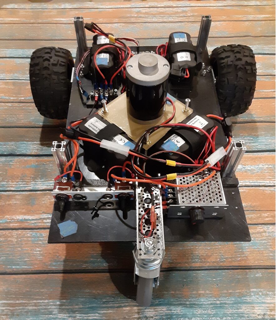
Main Chassis Rear View (3)
Main Chassis Bottom View (4)
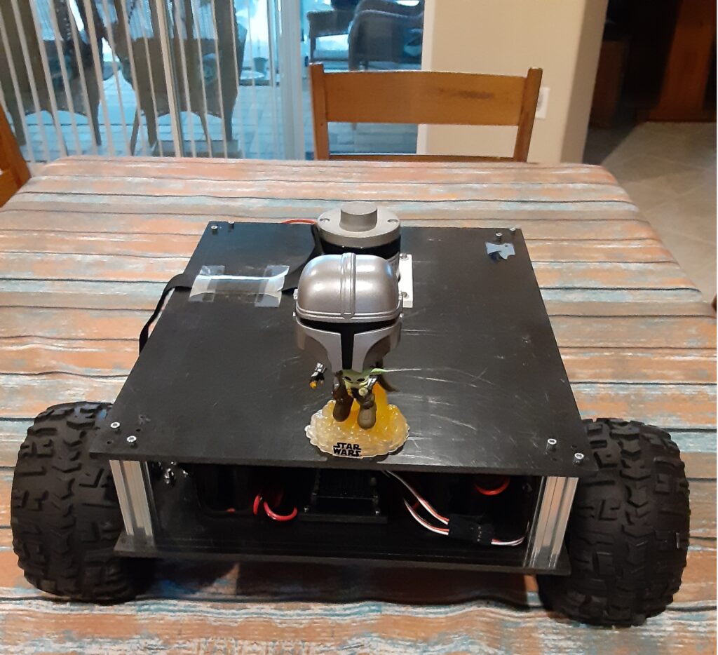
Chassis Upper Mounting Plate with Bobble Head Mandalorian and Baby Yoda (5)
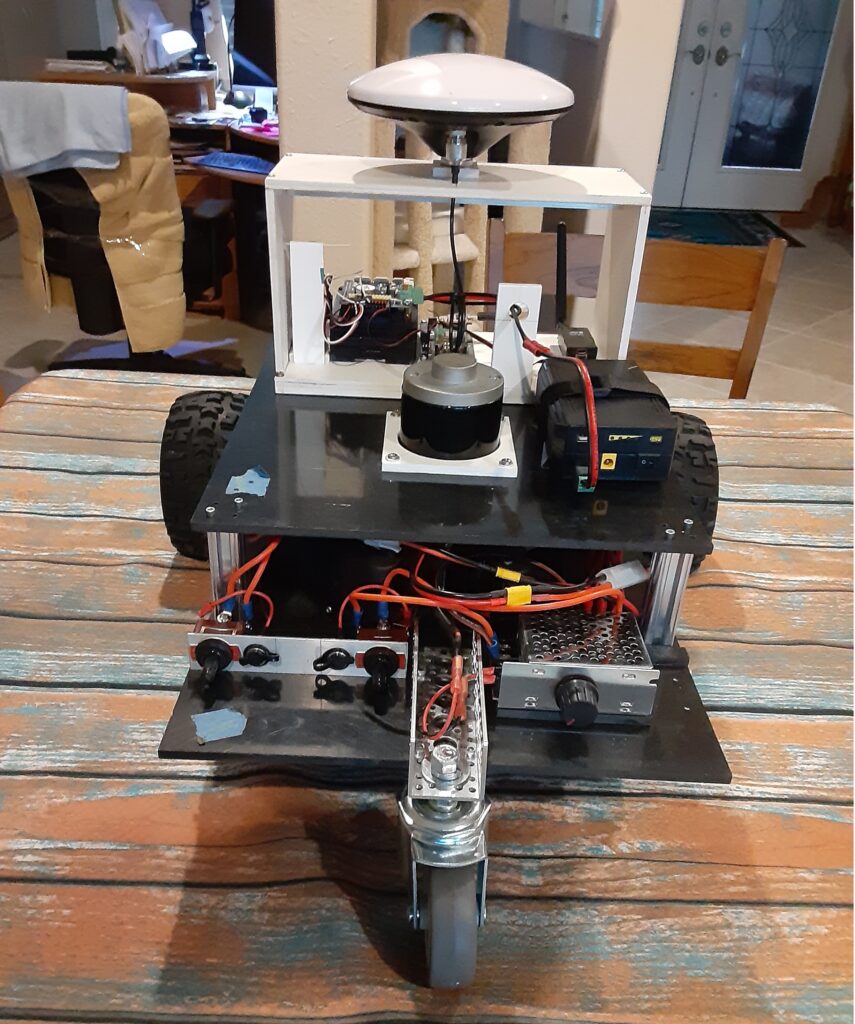
Rear of RTK GPS Guidance Module on upper Chassis (6)
I would like to build a bot to drop my seed pillows. I am thinking remote control with conveyor like system on top. Maybe up to 6 conveyors that can be top loaded. Any thoughts? gardengenius@outlook.com http://www.gardengenius.us
Hi Joel,
For accuracy you will definitely need RTK GPS for the Rover Bot which will require either a onsite Base Station or access to an NTRIP server to provide RTCM messages to the Rover Bot.
An inexpensive Base Station can now be built using the new Sparkfun RTK GPS (https://www.sparkfun.com/sparkfun-rtk-postcard.html), Sparkfun Portability Shield (https://www.sparkfun.com/sparkfun-portability-shield.html) and an appropriate L1/L2 GNSS antenna (https://www.sparkfun.com/gnss-multi-band-l1-l2-l5-surveying-antenna-tnc-spk6618h.html) and a Sik Radio pair for transmitting RTCM correction messages.
Information on an NTRIP server can be found here: https://ezward.github.io/gps/#u-center
The Bot Rover RTK GPS receiver can be built using the same components as the Base Station.
As far as the Bot chassis goes, I would have to see a picture of the rows/area to be seeded to provide some construction advice.
TCIII
This is an relatively old post. But GNSS RTK based DIY lawn mowers were around for quite some time;-) A lot was around https://ardumower.de. Some of my own versions:
https://www.youtube.com/watch?v=aDJ-oYfIqgM
https://www.youtube.com/watch?v=tLfbARcV1WM
https://www.youtube.com/watch?v=v4VH12zqEc0
https://www.youtube.com/watch?v=Duys_q16pEA