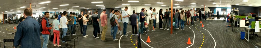
Starting with the March 7 Circuit Launch event, we’re going to be adding an outdoors track for cars using GPS or otherwise wanting more of a challenge than the indoor track. Although the outdoor track will be open all day (starting at 10:00am) of the event, the formal competition on that track will only begin after the indoor event has concluded, at 3:00pm, and conclude at 5:00pm.
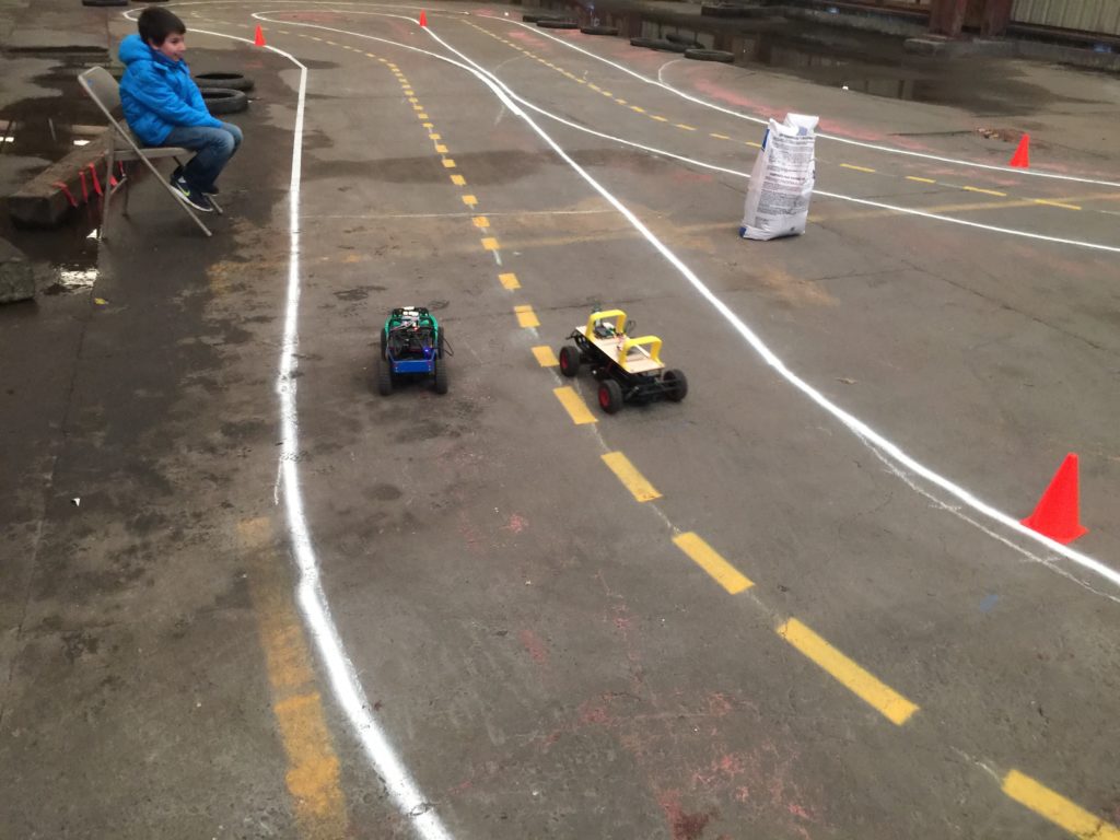
The below shows roughly where the track will be, in the parking lot at the side of Circuit Launch. There will be white tape marking the outside and inside of the track and cones placed at the corners. More details on the track and challenges (random cone obstacles, etc), will be announced on the day of the event.
To aid in GPS-guided navigation, we will have two RTK GPS base stations broadcasting. One is an Emlid Reach RS+, the other is a Swiftnav Piksi2. If you want to use either of these, you car must have a compatible “rover” GPS mounted on it. We recommend the Emlid Reach M+ (it can also work without a base station)
Regular GPS units will work too, of course, but will not be as precise as RTK GPS. But if that’s all you have, bring it and see how well it does!
BTW, if you’ve never tried GPS-guided autonomous cars, we recommend you start with the ArduRover project, which has been used successfully for years at the Sparkfun Autonomous Vehicle Competition (RIP), and uses the same Pixhawk autopilot hardware as many drones.
One of the most useful sensors to add to an autonomous car (after the camera) is an encoder. This “closes the loop” of motor control, giving you feedback on what actually happens when you send a speed command to the motor (the speed the motor actually turns can depend on a lot of things, from the battery voltage to the increased load on the motor going uphill, etc).
In a perfect world we’d have an encoder on each wheel, showing the actual rotation of each tire, which, slippage aside, should perfectly correlated to speed and distance traveled. But it’s too hard to retrofit most RC cars to add encoders on each wheel, so this post will show you how to do it the easy way, with a single encoder on the motor. That will at least give you motor speed feedback and since that shaft is distributed to all the wheels, it averages out quite close to car speed and distance.
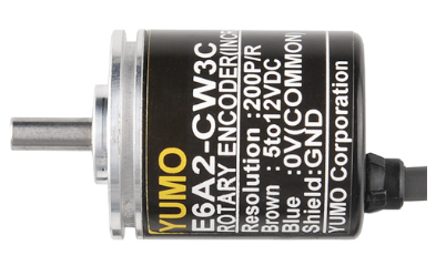
We’re going to be using “quadrature” encoders, which know the difference between forwards and backwards rotation and are easily read by a simple microcontroller. I’ll offer two alternatives that work the same, although one is cheaper (albeit larger) than the other.
I won’t be going into how to use this encoder information in your robocar, since it depends a lot on which software stack you’re using (Donkeycar, Jetracer, etc). That will wait for the next post. This one is just for the mechanical and electrical installation.
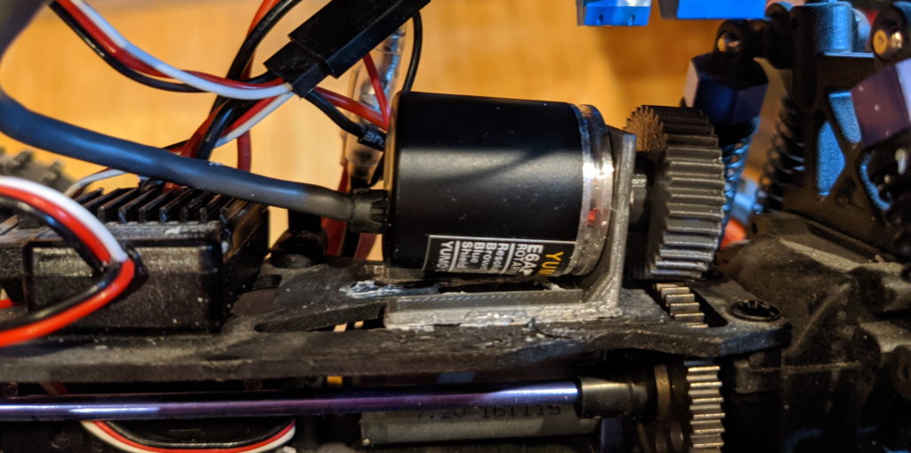
As you can see from the photo above, the standard Donkey chassis (the Exceed Magnet) has space to put the encoder above the motor where there is a large drive gear that is easily accessible.
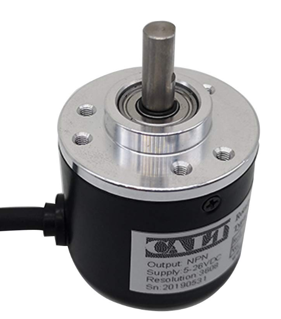
Your choices are pretty simple. The cheaper encoder below is bigger (38mm diameter) and weighs a bit more. The more expensive one is smaller (25mm diameter) and proportionately lighter. My picture above shows the smaller one, which is a slightly neater installation, but if you want to save a bit of money the larger one works just as well.
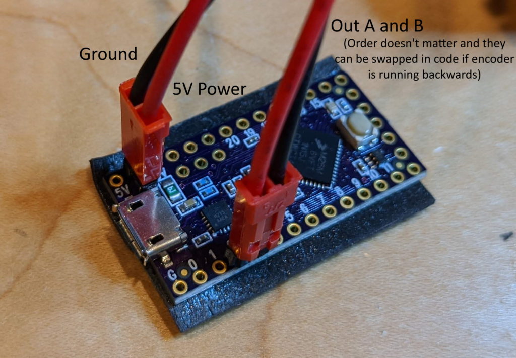
You’ll also want a microcontroller to read the encoder data, which is easier to do on something like an Arduino than it is on a Linux computer like a RaspberryPi or Jetson Nano. I use a Teensy LC for that, which is faster than a stock Arduino and nicely small. You can buy that from many places, such as PJRC ($11.65) or Amazon ($15.26). But any Arduino-compatible microcontroller will do, such as the Adafruit Feather series or an Arduino Mini.
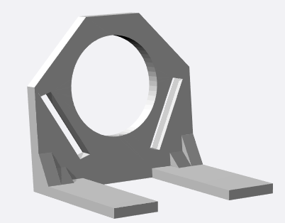
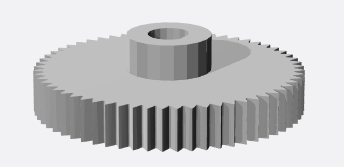
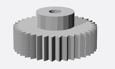
If you have a 3D printer, you can download the files for the mount and gear below. Or if you don’t, you can order them from the same link.
Cost
Encoder
Mount
Gear
$15.99 (plus $10 for 3D printing if you don’t have your own printer)
Just screw the encoder on the mount, press the gear on to the shaft, and position the encoder as shown above so that the gear seats nicely on the motor gear and turns with it, without slipping. You can glue the mount on the car chassis shelf when you have the right position.
Once you have the encoder in place, solder pins on the the Teensy board in the pins shown below (USB V+ and Gnd and Pins 2 and 3), cut the encoder wires to the desired length and splice female connector of any sort to them as shown. On the smaller encoder, there is a fifth wire (orange, called “Output Z”) that can be cut off and ignored.
On the Teensy (or any Arduino), you can run the standard Arduino encoder library to test the encoders. Just search for it in the Arduino Library Manager and install it. From the Arduino Examples menu, select the Encoder/Basic example and edit it to reflect the pins you’re actually using:
Encoder myEnc(2, 3);
Now you’re up and running! You should be able to open the Serial Terminal (9600 baud) in the Arduino IDE and see the values streaming as you turn the encoder. To use this with your robocar code, you’ll want to plug the Teensy/Arduino into your main car computer’s USB port with a short cable, where it should show us as a serial port. You can can then read the encoder values over serial and use them as you see fit.
More details on how to do that with the next post.
In the past year there’s been an explosion of good, cheap depth sensors, from low-cost Lidars to “depth cameras” with stereo vision and laser projection. It’s now easy to augment or even replace computer vision with depth sensing in DIY robocars, just like most full-size self-driving cars do. Intel has been leading a lot of this work with its great Realsense series of depth sensing and tracking cameras, which are under $200 and have a solid SDK and often built-in processing. This post is the latest in my tutorials in using them (a previous post on using the Realsense T265 tracking camera is here).
One of the ways to compare depth sensing cameras with Lidar (2D or 2.5D) is to use them to navigate a maze. There are lots of ways to navigate mazes, including very simple depth sensors such as an array of ultrasonic (sonar) or 1D laser range sensors (“time of flight”), but the common factor between a Lidar unit and a depth sensing camera is that they do more than those 1D sensors: they both return an array of pixels or points with depth information across a sweep of area around the vehicle.
The difference between these two kinds of sensors is that a spinning Lidar unit can potentially show those points around a full 360-degree disc. A depth camera, on the other hand, can typically can only see a rectangular area forwards like a solid state Lidar, with a horizontal spread of around 90 degrees. Unlike most solid state Lidars, however, a depth camera typically has has a much wider vertical spread (also around 90 degrees).
Camera tend to have shorter range than Lidar (10m max, compared to 20-30m max for low-cost Lidar) and lose precision the further they are from an object. On the other hand, depth camera are much higher resolution (a million points per second for a camera vs about 10,000 for a low-cost Lidar).
Cameras are also much cheaper: $180 for the RealSense 435 versus around $840 for the cheapest solid state Lidar, a Benewake CE30-A.
The purpose of this experiment was to see whether the Realsense Depth Camera could do as a well as a laser. Spoiler: it can! (see below)
A note about the computer I used for this, which was a Raspberry Pi 3. It doesn’t have enough power to really take advantage of the high speed and large data return from the Realsense sensors. However, I used it because I wanted to use the new Sphero RVR as the chassis, since it does a nice job of making all the motor driver and heading control simple and automatic, thanks to an internal gyroscope and PID-driven motor controller with encoders — you just tell it what direction to go and goes there, straight as an arrow.
The RVR can power your onboard computer with 5v via USB (it communicates with the computer via a separate serial cable). That limited me to computers that could be powered at 5v, which includes the Raspberry Pi series, Odroids and the Jetson Nano. However, there is also a low-cost x86 single-board computer (SBC) that Intel recommends, call the UP Board, and that runs on 5V, too. So if I was starting this again and I’d use that instead, since it should be able to install the Realsense SDK with a simple “sudo apt install” and “pip install”.
The second problem with the Rpi is that the Realsense SDK only works on Ubuntu (as well as Windows, although that wasn’t an option here). Although there is a version of Ubuntu (Ubuntu Mate) that works with the Raspberry Pi 3, support for the more powerful Raspberry Pi 4 is incomplete, and I couldn’t get Realsense to work on it. So Raspberry Pi 3 it was.
Compiling the Realsense SDK (librealsense) on the Rpi 3 can take a full day (unattended, thankfully) and you have to do it again every time Intel releases a new version, so that’s a bit of a hassle. So lesson learned: if you have an UP Board, use that. But if you happen to have a RPi 3, it will work, just more slowly.
Software
Enough of the hardware: let’s talk about the software! My approach to the maze-following task was to basically look at all the depth signatures in front of the car, with as wide a view as possible and a vertical “region of interest” (ROI) set as above the ground and not far above the height of the maze walls. I figure out which path has obstacles furthest away (ie, is most open) and head that way — basically go to where the path is clearest ahead. (This is mathematically the same as avoiding the areas where the obstacles are closest).
In my Python code, I do that the following way. Thirty times a second, the Realsense sensor sends me a depth map (640×480 pixels). To save processing time, I read every fifth pixel from left to right for each scan line within my vertical ROI (in this case from line 220 to 280), creating 128 “stacks”, each of which contains 60 vertical pixels, which is about 8,000 points in total. I then average the values within each stack and display them in a serial terminal in a crude character-based display like this (the smaller dots are the more distant obstacles, ie, the clear path ahead):
I then bin them in blocks of ten of these stacks, for a total of 13 blocks. Each block then gets an average and then I steer towards the block with the highest average (furthest distance). If I get stuck in a corner due to the relatively narrow field of view of the Realsense depth camera (“corner” = all visible directions have obstacles less than 0.75 meters away), I stop and rotate in 15-degree increments until I can see a clear path ahead.
It’s pretty simple but it works most of the time. That said, a simple 360-degree 2D lidar would do even better in this course, since it would be able to see the best open path at all times without having to stop and rotate. For that matter, a simple sonar “stay 10 cm from the right wall” method would work equally well in this idealized environment (but not in a real-world one). So perhaps a maze is not the best test of the Realsense sensors – a more open-world environment where they are used for obstacle detection and avoidance, not path following, would show off their advantages better.
Lessons learned:
Don’t use Raspberry Pis for Realsense sensors. Use Up boards or Jetson Nanos instead
Depth cameras are as good and way cheaper than solid state Lidar for short-range sensing
That said, 360-degree sensing is better than 90-degree sensing
The Sphero RVR platform is easy to use. It just works!
Thanks to the astoundingly productive Tawn Kramer, I’ve had a chance to play around a bit with his Donkeycar fork that uses the impressive Intel Realsense T265 visual odometry “tracking camera” instead of a regular RaspberryPi camera. Since Tawn’s original work, the Intel Realsense team has released a number of performance improvements for the T265, so it tracks even better now.
I also decided to use a processor with more power than the Raspberry Pi 3 that Tawn used, so I went with the Jetson Nano, which is the only other non-X86 single-board computer I was able to get the Realsense SDK working on (it won’t work on a Raspberry Pi 4, since Ubuntu Mate, which is required, doesn’t run on that yet. Realsense will work on any X86-based SBC, such as an Up Board or LattePanda, but those are a bit more expensive).
It took a while to get all this working, so this post is just a summary of the steps needed.
Steps:
Follow the Donkeycar installation on Jetson Nano. But when you get to the part about cloning the Donkeycar code, use my fork instead: git clone https://github.com/zlite/donkey.git
Setup your Joystick, following these instructions. (update: see TCIII comment below for updated instructions) I used a PS4 controller (see TCIII’s comment below if you’re using an Xbox controller). Note that you’ll have to pair it via Bluetooth with the Nano. I did that in the Nano’s desktop interface by selecting the Bluetooth icon and adding the controller as a Bluetooth device when it was in pairing mode. The instructions say to set the driver to start at boot by editing the rc.local file, but you may find that the Nano doesn’t already have one. No worries, just create it from scratch and add the necessary line like this:
sudo nano /etc/rc.local
paste /home/pi/env/bin/ds4drv --led 00ff00 into the file. Save and exit.
If you’re using a PS3 controller, in manage.py change this line to say this:
cont_class = PS3JoystickController
Set bus num to 1 in myconfig.py:
PCA9685_I2C_BUSNUM = 1
After you’ve done that, set up the directory with this:
Once it’s running, open a browser on your laptop and enter this in the URL bar: http://<your nano’s IP address>:8887
The rest of the instructions from Tawn’s repo:
When you drive, this will draw a red line for the path, a green circle for the robot location.
Mark a nice starting spot for your robot. Be sure to put it right back there each time you start.
Drive the car in some kind of loop. You see the red line show the path.
Hit X on the PS3/4 controller to save the path.
Put the bot back at the start spot.
Then hit the “select” button (on a PS3 controller) or “share” (on a PS4 controller) twice to go to pilot mode. This will start driving on the path. If you want it go faster or slower, change this line in the myconfig.py file: THROTTLE_FORWARD_PWM = 530
Check the bottom of myconfig.py for some settings to tweak. PID values, map offsets and scale. things like that. You might want to start by downloading and using the myconfig.py file from my repo, which has some known-good settings and is otherwise a good place to start.
Some tips:
When you start, the green dot will be in the top left corner of the box. You may prefer to have it in the center. If so, change PATH_OFFSET = (0, 0) in the myconfig.py file to PATH_OFFSET = (250, 250)
For a small course, you may find that the path is too small to see well. In that case, change PATH_SCALE = 5.0 to PATH_SCALE = 10.0 (or more, if necessary)
If you’re not seeing the red line, that means that a path file has already been written. Delete “donkey_path.pkl” (rm donkey_path.pkl) and the red line should show up
It defaults to recording a path point every 0.3 meters. If you want it to be smoother, you can change to a smaller number in myconfig.py with this line: PATH_MIN_DIST = 0.3
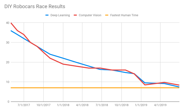
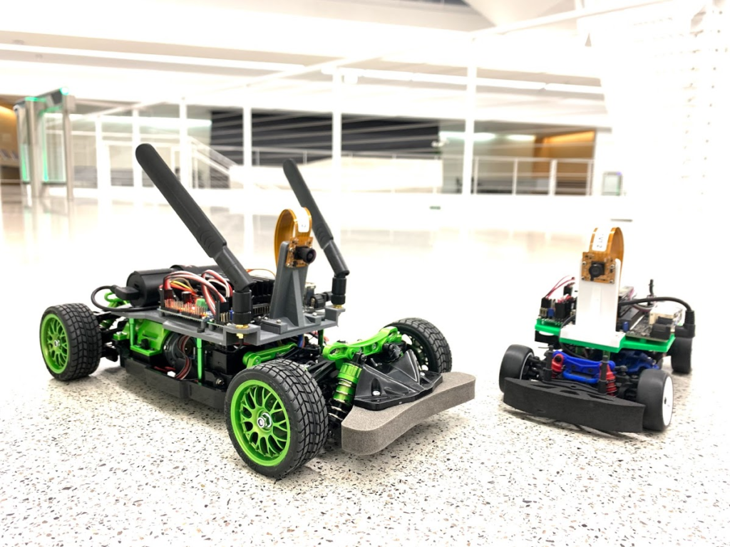
As you know, the DIY Robocars races are partly about beating other cars, but they’re also about beating puny humans. And we’re getting pretty close!
But see that yellow line at the bottom representing the “fastest human time”? That time was set almost a year ago by a human who…let’s put this gently…may not have been the fastest RC driver on the planet. Or possibly even in the room.
So now it’s time to give the humans a chance to defend themselves better before those red and blue lines cross the yellow and our species is rendered unnecessary.
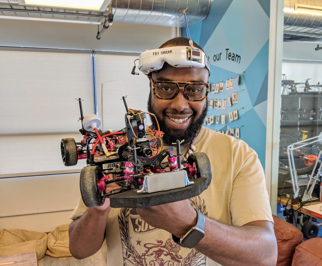
Enter Ross Robinson (above)! By day he’s a robot wrangler at 3DR (as am I), but unlike the rest of us geeks, he’s pretty good at driving a car. And he not only has a fast one, but it’s set up with a camera for First Person View driving, so his view of the track will be exactly the same as the autonomous cars!
So, starting with the Sept 21st event, the last race of the day will be the fastest robot car vs the fastest human present. The first one will be Ross.
No pressure, Ross, but the fate of humanity lies in your hands
Along with the fantastic $99 Jetson Nano, Nvidia has released two DIY car kit guides to use the Nano for real-world robotics. I’ve built and got them both working, so this is a quick overview of the two and some tips and tricks. (There’s also a good hands-on of the Jetbot at ExtremeTech, which is worth reading, too)
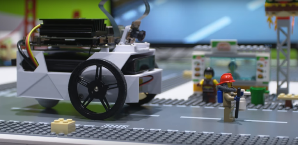
The Jetbot is designed to use computer vision and AI to navigate small areas slowly, such as the Lego-scale roads shown here, to demonstrate basic self-driving car techniques.
The parts are available in various options:
Order them all separately from this list (about $150)
Kit from Adafruit ($34.95, requires a Jetson Nano, the 3D printed parts, camera, wifi, battery and a few other parts from the list above)
Just the 3D printed parts ($35), if you don’t have your own 3D printer
Sparkfun is also planning their own kit ($274), which looks a little too cobbled together for my taste, so that wouldn’t be my first choice
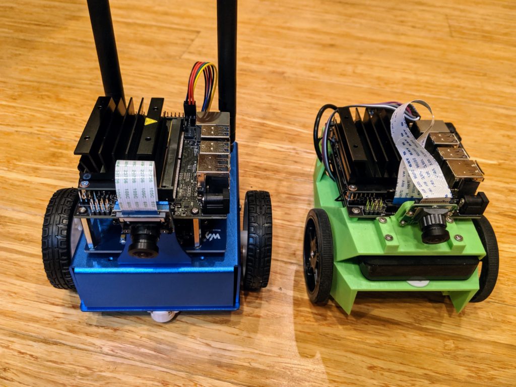
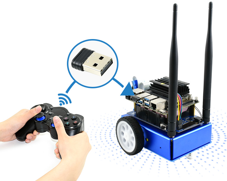
Waveshare also has its own 3rd-party variations of the Jetbot, which improves on the original with a metal chassis and integrated electronics (see below). This seem to be the best deal, at $219 INCLUDING a Jetson nano, but I haven’t tried it myself. Update: now I have and it’s terrific. Short review here, but here’s it next to my DIY version:
However, the Nvidia team has tried it and they like it a lot, especially with its integrated battery charging, so that seems like the best bet if you don’t want to get and make the parts yourself.
What can it do?
The basic examples are collision avoidance and object following, both of which use the Nano’s deep learning abilities and Jupyter Python interface for training well. Here’s one example of it working:
A new example, which you’ll find on the on-board Jupyter notebooks but not the wiki yet, is road following. I trained it on my patio track, which is meant for larger vehicles that can roll over the tile bumps, but despite what must have seemed like pretty rough terrain for this little bot, it made it around the track pretty well:
More to the point, this is a general purpose AI platform. Anything that can run on a Jetson can run on this (within the limits of the Nano’s processing power): TensorFlow, Keras, OpenCV, etc. It’s running a flavor of Ubuntu Linux, so DonkeyCar works, and you can even train locally (as opposed to in the cloud)! The only limits are the small and slow car…
…Enter JetRacer!
JetRacer is more than just JetBot on a faster RC chassis. The Nvidia team also increased the speed of the software processes, including increasing the camera frame rate and optimizing TensorRT to handle the speed of the vehicle.
It’s also got a simplified training scheme to gather data faster. Like JetBot, it uses “supervised learning”, which is to say that you, as the human, put the car on the track and point to where it should drive in various different positions. You do that about 50 times, train for 5 minutes, and then it can drive itself. On JetBot, this involves using a joystick to point to a path. On JetRacer, you just click on the spot it should drive to (no joystick required).
Now, you’ve got a vehicle that can compete in a DIY Robocars race. This isn’t a good example of a proper track (my patio isn’t big enough) but it will give you a sense of how it compares to JetBot, above:
Here it is training on the beginners track at the proper DIY Robocars track at CircuitLaunch:
The standard JetRacer chassis is a 1/18th-scale Latrax model, which has a 7″ wheelbase. That’s plenty fast for me (and it qualifies for the “Stock” DIY Robocars category), but if you want to go even faster, they support a 1/10th scale version based on the Tamya chassis, which I think can compete with the fastest cars we have.
A final note on the Jupyter notebooks Nvidia supplies for road training. They’re good, but confusing. The process goes like this:
Gather data by recording 50 images or so, with human suggestions on where to steer for each
Train with those images
Check your trained model with some live video from the car on the track, to see if the blue dot (“steering target”) is pointing to the right place to drive to
Run it live on the car, tuning various parameters for the best performance
Right now, those four steps are combined into two Jupyter notebooks, which is both confusing and tends to bog each down with unnecessary processes running in the background. My advice to the Nividia team would be to split them up a bit more. #1 above should be one notebook. #3 should be another, and #4 should also be a stand-alone, with interactive sliders that work in real-time to adjust driving parameters, exactly as JetBot does.
So, in summary, JetBot is easy to use but slow. JetRacer is fast, but hard to use. Memo to Nvida: Combine the best of the two and you’ll have a winner!
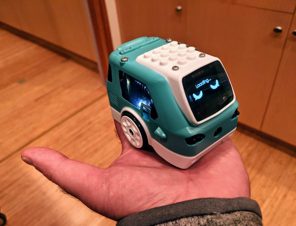
First of all, it’s ADORABLE! So small, it can fit in the palm of your hand, but has a RaspberryPi ZeroW, and Arduino, a screen, camera, loads of sensors and LEDs all inside.
Zumi started as a Kickstarter project and just shipped to first backers (I was one) last week. You can now buy it directly from its creators, Robolink, for $139. Details are here.
My first impressions were very positive, despite the usual first-batch problems with Kickstarter projects (a few missing bits in the kit and some instructions that aren’t quite accurate). It was easy to put together and once I fixed a boneheaded mistake (if you plug in the screen connector backwards, the car won’t boot at all — yikes), it booted up fine and coached me through the process of connecting via wifi and updating its firmware.
So what can it do? The initial Kickstarter pitch focused a lot on computer vision and AI, but it’s clear that many of those videos were done on beefier computers than the RaspberryPi Zero in Zumi. The current package is more limited, with no real machine learning at all.
Nevertheless, the initial lessons are a lot of fun and show the solid Python functions Robolink has shipped with Zumi. Examples start with how to use a Jupyter notebook, and then move to sensors (IR distance/obstacle, gyro and accelerometer), LEDs and the buzzer and of course motion. Although Zumi’s motors don’t have encoders, it uses the gyro to go straight and turn by set amounts, which works well.
Once you get to computer vision, the limits of the RaspberryPi Zero, hobbled by the overhead of the Jupyter server and wifi streaming, show up. Lessons in object tracking, face and smile spotting and color spotting all suffer from terrible lag and several can not finish at all.
Although Robolink promises more is coming with updates, it’s hard to see how they can squeeze much more about RPi Zero using Jupyter. Although Jupyter is a great way to combine documentation, code and graphical output on one screen, it’s really designed to run on faster computers and slows to a crawl on Zumi if the camera is used. Robolink intends to release a different IDE in the future, perhaps one more like their Blockly interface, and that may work faster.
Once Robolink fixes the performance issues (perhaps by switching out Jupyter for a faster IDE) I think computer vision, including lane following and object detection, should be doable. Basic machine learning (with models trained in the cloud and only run locally) should also be possible. And who knows — maybe the Rasperry Pi Foundation will release a faster RPZero someday?
But for now, Zumi is really nicely designed and super-cute robot car at a reasonable price with a lot of room to grow.
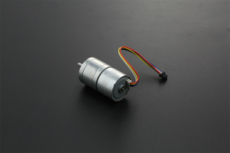
DF Robot has an interesting new robotics motor ($19), which has both the motor controller and the encoder integrated into the body. That means that you can drive it straight from an Arduino, with no separate motor controller required. That’s pretty cool and leads the way to very simple rover setups.
The motor is 12v (good choice for a 3-cell, 11.1v lipo battery), geared to max 159 rpm. It’s smaller than the usual robot motors, but has enough power for a small rover.
Because it’s so well integrated with controller and encoder, it’s a good way to demonstrate proper PID motor control. So here’s a demo! The code is here:
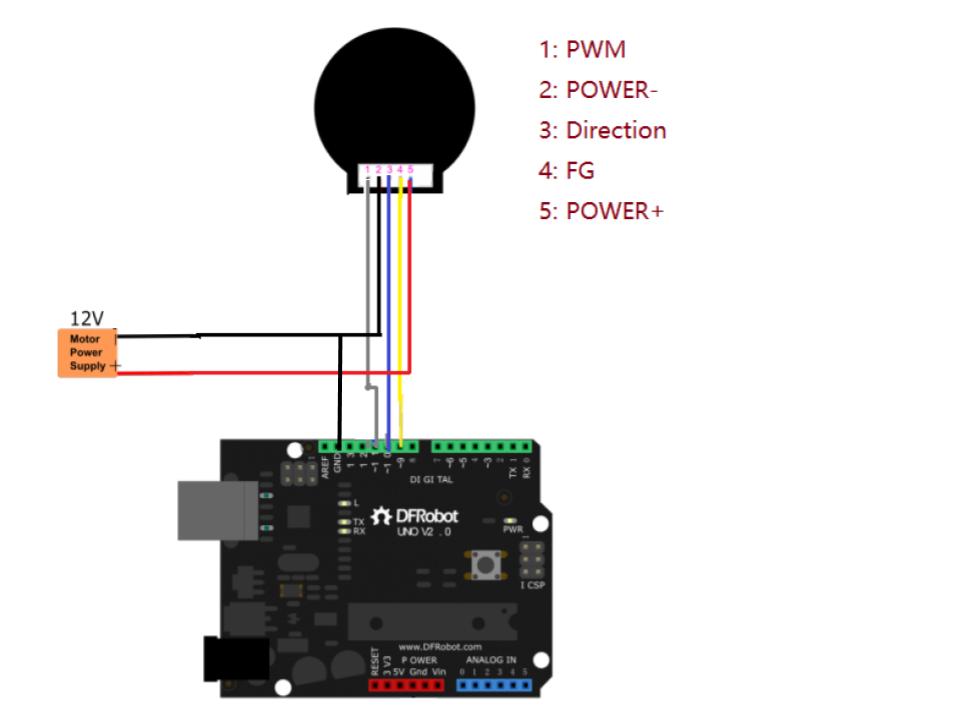
Connect it to an Arduino like this (the wire colors will probably be different; pay them no mind. Just keep the red and black right and connect the others in the following order). Important: you must also connect the Arduino ground to the 12v power supply ground as shown):
Now try it with a PID controller, which will maintain a desired RPM within a reasonable range (80-140 rpm). Here’s some Arduino code that will do that.
Try playing around with the Kp (proportional), Ki (integral) and Kd (derivative) terms in this code and see what happens when you enter a different speed (80, 100, 120, etc). With the stock settings below, the Ki term will slowly build up so the RPMs approach the desired speed. A higher Kp term will speed up that convergence, but too high will overshoot. Here’s a short video that gives the basics, but the key points is that it uses feedback.
You want the speed of the motor to be a certain value, but just commanding it to go to a certain power doesn’t mean that it will get to exactly the desired speed (because of variation in battery voltage, etc). So rather than just sending a command and hoping for the best, you measure the actual speed the motor is turning with the encoder. Then just keep changing the motor control inputs until the motor speed output is close to the desired one — that’s what a PID controller does. All the various settings (P. I. D.) are just to tune it so it does that well.
// Make sure you've added the official Arduino PID library to your libraries
 // https://playground.arduino.cc/Code/PIDLibrary/
 include
 int i = 0;
 int rpm;
 unsigned long time = 0;
 bool direction = HIGH;
 int speed;
 double Setpoint, Input, Output;  // Setpoint is going to be the desired speed. Input will be encoder reading. Output will be motor command
 double Kp = 0.5;
 double Ki = 3;
 double Kd = 0;
 //Specify the links and initial tuning parameters
 PID myPID(&Input, &Output, &Setpoint,Kp,Ki,Kd, REVERSE);
 void setup() {
   Serial.begin(115200);
   pinMode(10, OUTPUT); //PWM PIN 10  with PWM wire
   pinMode(11, OUTPUT);//direction control PIN 11 with direction wire
   digitalWrite(10, direction);
   Setpoint = 100;
   Input = 100;
   myPID.SetMode(AUTOMATIC);
 }
 void loop() {
   if (Serial.available())  {
     speed = Serial.parseInt();
     speed = 255 - speed;
     delay(200);
   }
   for(int j = 0;j<8;j++)  {     i += pulseIn(9, HIGH, 500000);         //SIGNAL OUTPUT PIN 9 with  white line,cycle = 2i,1s = 1000000us,Signal cycle pulse number:272   }   i = i >> 3;
   rpm = 111111 / i;   //speed   r/min  (601000000/(4562i))
   i = 0;
 //  Serial.print(rpm);
 //  Serial.println("  r/min");
 Setpoint = 255-speed;
   Input = rpm;
   myPID.Compute();                       // calculate the right motor control to make rpm equal desired speed
   if (Output > 220) {Output = 220;}
   if (Output < 20) {Output = 20;}
   Serial.print("Setpoint, Input, Output: ");
   Serial.print(Setpoint);
   Serial.print("  ");
   Serial.print(Input);
   Serial.print("  ");
   Serial.println(Output);
   analogWrite(11, Output);
 }
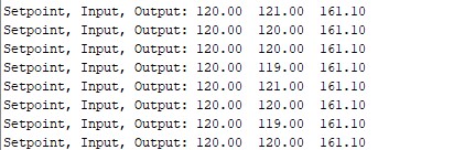
If you enter a desired RPM between 80 and 130 in the Arduino Serial Terminal it will try to hit that number. Output should look something like this (“Setpoint” is PID-talk for “desired speed”. “Input” is the reported speed from the motor encoder. “Output” is the motor control signal [0-255] that the code sends the motor):
Now that the DIY Robocars quarterly races in Oakland have gotten big and the cars fast, it’s time to evolve the rules to reflect our learnings over the past two years.
As of the Sept 21 2019 race, these are the new rules:
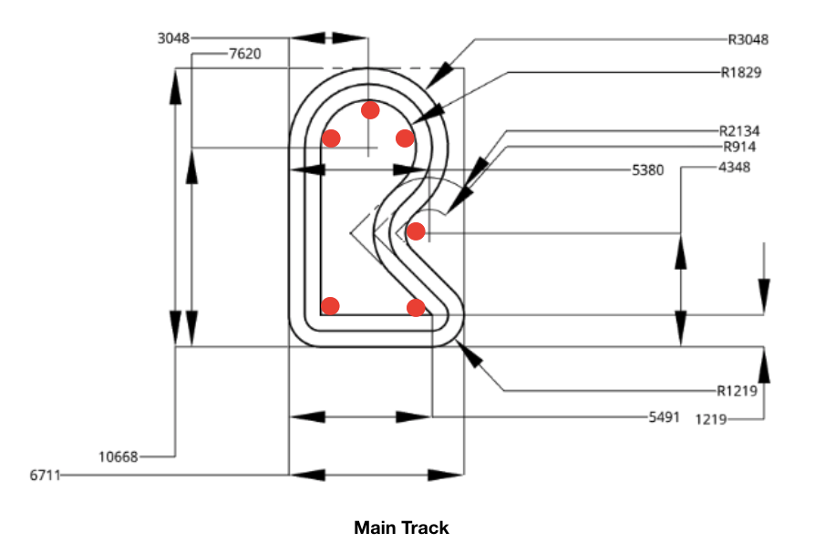
There are two tracks, one for beginners and a main one for returning racers:
There are 12″ orange cones on the inside of every curve, as shown above.
There will be one “obstacle cone” placed at a random location (changed with every race) inside the track.
The Beginners Track has the same shape, but is about 25% smaller
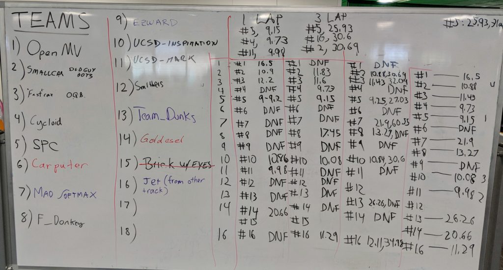
If this is your first race or your car’s first race, you must start on the Beginners Track. There will be one judge on that track to schedule official runs. If you can successfully complete a lap in under 40 seconds, you may advance to the Main Track and place your team name on the lineup board (example from a recent race shown below).
Main Track Rules:
Cars:
Cars must start with a single binary interaction. This could be a button on the car, on a controller, a key on a keyboard or equivalent. No other intervention can happen until after the race is over; otherwise the car gets a “did not finish” (DNF). An emergency stop button is recommended but not required. Deadman’s switch is also acceptable where button is pushed and held for the duration of the race.
There are no rules governing where the computing needs to take place. Cars may have onboard computing, trackside computing or leverage remote or cloud resources.
GPS and other similar positioning systems are not allowed except for specified outdoor races.
The desire is that this is an open source league and that all designs are put on github and are readily copyable after the conclusion of every race. If you are prevented from open-sourcing designs or prefer not to, there is no obligation to do so.
There are two categories of racers: Stock and Unlimited
1) Stock:
This includes all the standard platforms: DonkeyCar, JetRacer, DeepRacer as well as any custom vehicles that satisfy the below criteria
Cars are 1/16th scale or smaller: No more than a 7.5″ (190mm) wheelbase, axle to axle.
Cost no more than $400 all told (car, computer, sensors, etc)
Batteries must be firmly attached with velcro or other straps so they can’t come loose during the race
2) Unlimited:
This is for cars larger and/or more expensive than Stock
Cars may be up to two feet long and may weigh up to 10lbs
No limit on cost (although we do encourage DIY economics — if you’ve spent $10,000 on a Lidar sensor, this may not be the right event for you. Not only is it out of reach for others to follow, but in the obligatory Demolition Derby at the end it may very well get damaged)
Batteries must be firmly attached with velcro or other straps so they can’t come loose during the race
Races:
There are three heats, followed by a “ladder” race-off of the top six cars, paired by closest times, ending with a final race between the top two cars for the winning trophy (not actually a trophy!).
All races will be “wheel-to-wheel” with two cars on the track at the same time
Every car will have at least three opportunities to race. Only those in the top six will move on to the ladder.
The first heat pairings are random, within the class they have entered. After that, the second and third heat pairings are based on matching closest times within their class in the first heat.
Racers may choose to agree on track starting position (inside or outside lane). If they do not agree, the judge will flip a coin to decide.
The final race is an all-cars Demolition Derby. If you brought a car, even if it didn’t qualify for the Main Track or even if it doesn’t even work autonomously, you will race. There will be crashes. It will be fun. It’s the best 30 seconds of mayhem of the day.
Scoring:
Each heat is three laps. Both the first lap and the three-lap times will be recorded for each car, but only the first-lap time will determine ranking for the next heat (or ladder position)
Passing any “curve cone” on the inside is immediate disqualification for that heat
There is no penalty for going outside the white lines, as long as you don’t violate the cone rule above
The random “obstacle cone” may be passed on either side. Hitting the obstacle cone imposes a two-second penalty
Now that our computer and software platforms have improved to the point that we’re reaching the maximum physical speed of cars on regular “kidney-shaped” track without resorting to crazy tires and motors, it’s time to slow things by adding more challenge on the CV/AI side.
There are three standard ways to do this:
1) Always race with at least one other car (“wheel-to-wheel” racing). These “moving obstacles” introduce both randomness as well as the need for smart race tactics to win. Those include:
Spotting other cars
Deciding to pass on the inside or outside
Picking the right time to pass (straightaway, before a curve, after a curve)
Using AprilTags or other standard computer-readable markers on the back of each car to make them easier to identify
2: Place a cone or other obstacle in the track at some random location before each race. This introduces the following challenges:
It breaks naive “cone trackers” that assume that cones are stationary and always at the outside of the track
Requires car to differentiate between “outside” cones (which mark the outside of the curves and must always be passed inside and not touched) and “inside” cones (which can be passed on either side)
Requires cars to do more than just track the road lines
3: Static obstacles, such as gates, ramps or simulated pedestrians (like the above, from the Sparkfun AVC 2018). This can introduce a number of unique challenges and fun scoring opportunities:
Having to differentiate by kind of obstacle, such as “pass to right of blue cone but to left of red cone”, or “some blue ramps add points if jumped, but others have spikes and will stop your car”.
Offer extra points (or subtracted seconds) if the car successfully passes through a hoop or between two markers in tight bottleneck
More advanced path-finding and decision-making, such as “stop for two seconds if a stop sign is detected” or “stop for detected pedestrians but just steer away from other obstacles”