How to display your Linux computer’s IP address on a LCD (and a few ways not to)
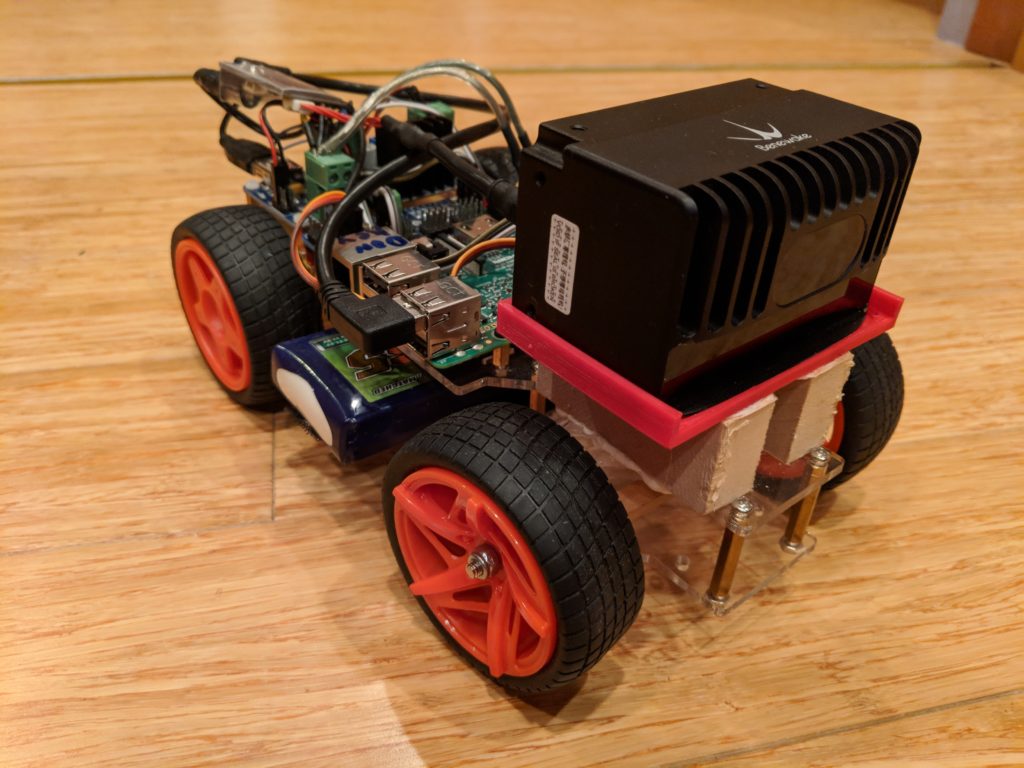
In a “headless” configuration (no screen or keyboard) such as typical in Raspberry Pi or other embedded computers in small robocars, one of the biggest hassles is figuring out what IP address the computer has been assigned over Wifi on the network you’re connecting to. There are some tools, such as Adafruit’s PiFinder, that will search a network to find connected RPis, but in my experience on large corporate networks they usually fail.
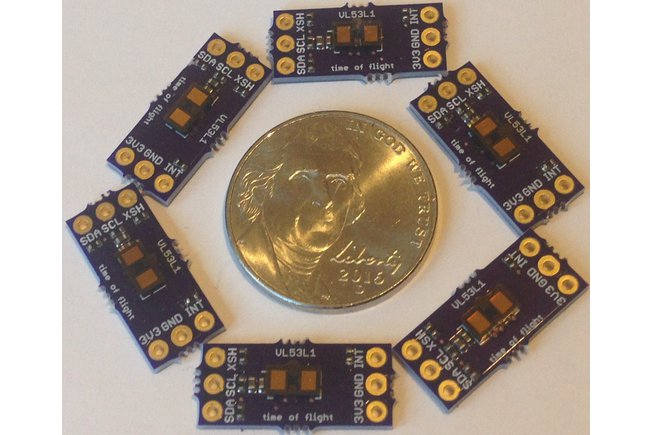
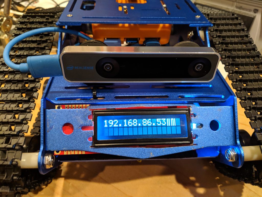
A better way is for the computer to display its own IP address once it boots and connects. But on small cars you don’t have room for a HDMI monitor, so you’ve got to connect a small LCD or OLED screen, such as these I2C or SPI displays from Adafruit or just a serial display like these. That’s easy enough to hook up, but how do you get the computer to automatically display on these displays its IP address when it boots up?
Google around and you will find many suggestions for autorunning programs at boot, especially for Raspberry Pi, which are a constant source of headless headaches. The problem with most of these is that they don’t work anymore. The main reason is that Debian (and, by extension, Raspian, the Linux varient that RPi runs) has changed some key functions in recent releases, breaking old methods. So, for example, putting the startup script in rc.local doesn’t work in current distros. Nor does putting it in etc/network/interfaces. All of these are ignored in the latest Debian/Raspian/Ubuntu releases.
Even worse, the hard part about this particular startup problem is that you can’t just run the program at startup, but you have to wait until it connects to a network and *then* display the IP address.
The solution is a method that uses the Linux “cron” function, which still works in current distros. Here’s what to do, using a serial LCD screen connected via USB on ttyUSB0:
- Edit your startup cron file by entering “sudo crontab -e” from the command line.
- That will ask you for an editor. Pick nano. In nano, type ”
@reboot /home/[your username]/startup.sh”, then press control-o and then control-x to save and exit. (To explain that line we just entered, it means “at reboot, run the startup script “startup.sh” in the user’s home directory) - Now go to your home directory and type “sudo nano startup.sh”, which will create that file
- If you’re using a serial LCD as shown above, type or paste this into that startup script, and then again pressing control-o, control-x to save and exit:
#!/bin/bash
sleep 10
ip addr | grep 'state UP' -A2 | tail -n1 | awk -F'[/ ]+' '{print $3}' > /dev/ttyUSB0
- 5. The above line waits for 10 seconds for the network connection, then uses the “ip addr” command to get the IP address. It searches for the network connections that are working (“up”) and returns the IP address, piped to the serial port at ttyUSB0
- 6. Now make sure sure startup.sh is executable by typing this in the command line:
sudo chmod +x startup.sh
Now it should start at next boot, wait 10 seconds, and then send the assigned IP address to a serial LCD screen.
There are better ways to do this, including a script that keeps running through a loop until “state UP” returns true, thus avoiding the fragile delay function, which might fail if the network connection hasn’t been reached in 10 seconds. But this works for me.
BTW, if you’re using an I2C or SPI screen, you’ll be better off calling a Python program that has a library to control it, rather than the simple serial LCD I used. But that’s more complicated, so I’ll leave it to another day.