Using the RC Hat
If you’re converting an off-the-shelf RC car to full autonomy with Donkeycar, one of the questions you may have is why you can’t use the RC controller the car came with instead of using a Bluetooth gaming joypad. The old answer was that the RC signal has to go through the RaspberryPi and be processed or bypassed by the Python code, depending on whether you’re in manual or autonomous mode, and there’s no good way to just insert the RaspberryPi into that process (even if you could plug your RC receiver cables into the RaspberryPi, it can’t properly handle those signals nor those necessary to drive your servo or motor controller output). Thus our old advice was to throw out your RC transmitter and receiver and use the gaming joypad instead along with an I2C servo controller board.
But now we have a better answer! The new RC Hat, which plugs on top of the Raspberry Pi, allows you to use your RC transmitter and receiver as is, without needing a joypad or servo driver board. Not only does that save you money, but the RC gear has way longer range, which is great for outdoors racing or racing around lots of other cars.
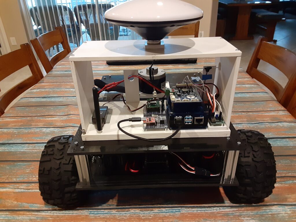
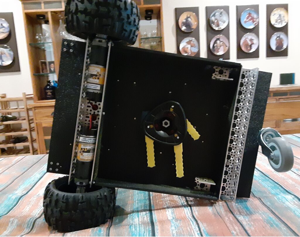
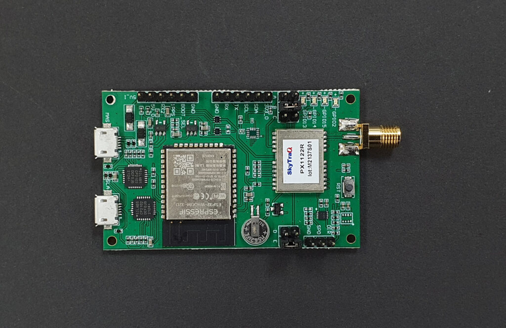
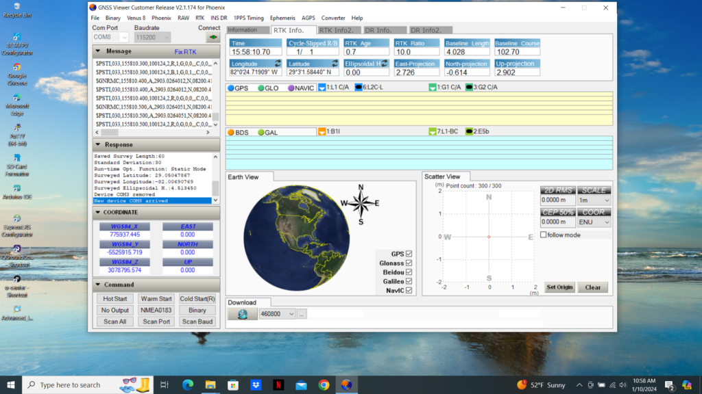
The RC hat consists of a circuit board that has a RaspberryPi 2040 Zero board on it, along with an OLED screen and the pins to plug in your RC receiver, your servos, as well as wheel encoders, other I2C devices and anything that needs 5v power. The 2040 board handles all the low-level reading of RC input and servo output and communicates with the RaspberryPi over hardware serial. The CircuitPython code for the RP2040 is here, although that’s already loaded on the board so you shouldn’t need to mess with it. 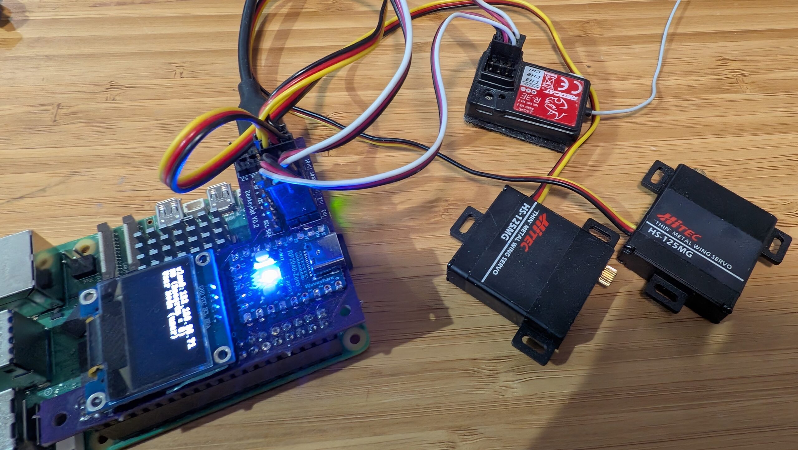
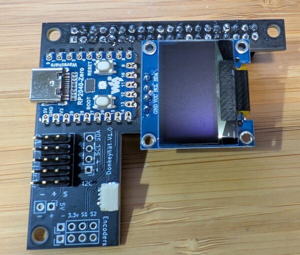
Simply use female-to-female 3-wire RC cables to connect your RC receiver into the “In 1”, “In 2” and (if you have a third channel) “In 3” pin headers. Plug your steering servo into “Steer” and your motor controller/ESC into “Throt”. Make sure you get the orientations right — black (ground) should always be on the outside next to the board edge.
To use it the hat, you’ll need to edit your myconfig.py file in your mycar directory. Make the following changes:
To enable the OLED screen, uncomment these lines and change the values as shown in the relevant areas of the myconfig.py file:
USE_SSD1306_128_32 = TrueSSD1306_RESOLUTION = 2 To enable the RC hat as output, in the “Drive train” section, uncomment and edit to this:
DRIVE_TRAIN_TYPE = "MM1"To enable the RC hat as input, in the “Joystick” section, uncomment and edit to this:
USE_JOYSTICK_AS_DEFAULT = True
CONTROLLER_TYPE = 'MM1'
In the “Robohat MM1 controller” section, uncomment and edit to this:
MM1_SERIAL_PORT = '/dev/ttyAMA0'Since you probably only have 2 or 3 channels on your RC gear, all other commands and mode changes will be done via the web interface (on joypads you use dedicated buttons) via Wifi. Instructions for that are here.
The screen will come on and show the Donkey state when you start Donkey via the usual “python manage.py drive” command. It won’t be on when you’re not running Donkey, although it’s there to be used for other programs if you’d like (it’s just a standard I2C OLED screen and can be used with this Python library).
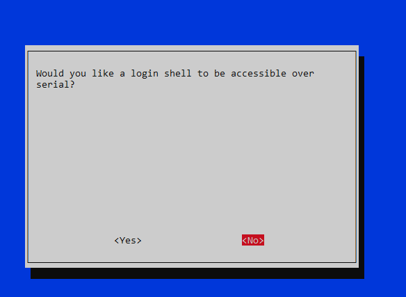
Finally, you’ll have to enable the hardware serial on the Pi. You can do this with “sudo raspi-config" Interface Options/Serial Port, which you will have already used to enable the I2C interface when setting up donkey.
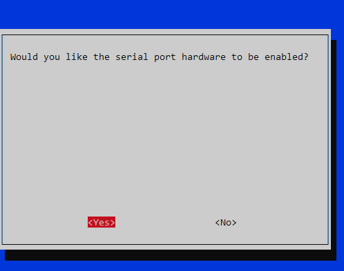
If you’re using a RaspberryPi 5, that all you need to do. If you’re using a RaspberryPi 3 or 4 (or Pi Zero 2), which weirdly share the hardware serial and Bluetooth interfaces, you need to do one more thing:
You can either use “ttyS0” as the serial port in the “MM1_SERIAL_PORT” setting in your Donkeycar myconfig.py file (instead of “ttyAMA0” as described above). This should work fine, but the baud rate can vary a bit with clock speed with this approach. That hasn’t shown itself to be a problem in practice, but if you want to be safer, you can disable the Bluetooth and use the HW serial as intended at ttyAMA0:
Add this to the bottom of config.txt (enter “sudo nano /boot/firmware/config.txt"):
dtoverlay=disable-btType Ctrl-O, Ctrl-X to save and exit the Nano editor
Then enter this in the command line:
sudo systemctl disable hciuart
Reboot when you’re done and it should all work!