Using the Intel Realsense T265 and the Jetson Nano for a robocar

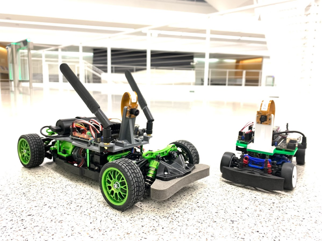
Thanks to the astoundingly productive Tawn Kramer, I’ve had a chance to play around a bit with his Donkeycar fork that uses the impressive Intel Realsense T265 visual odometry “tracking camera” instead of a regular RaspberryPi camera. Since Tawn’s original work, the Intel Realsense team has released a number of performance improvements for the T265, so it tracks even better now.

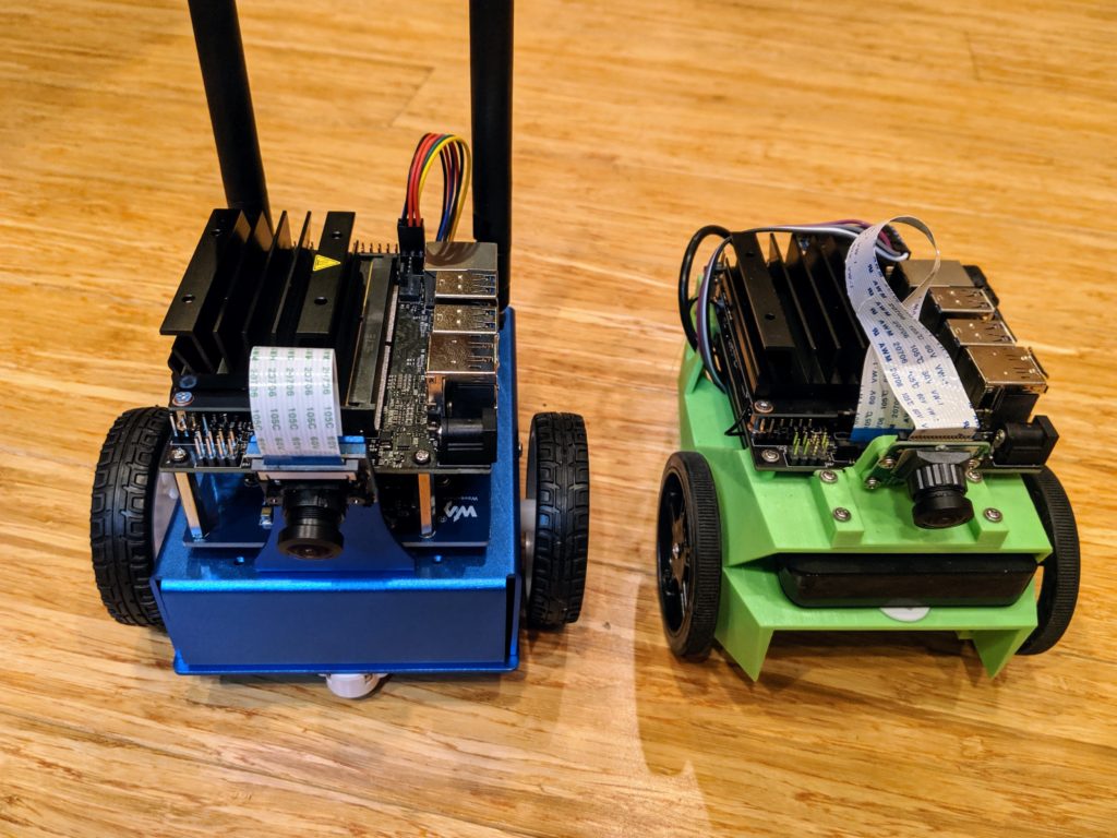
I also decided to use a processor with more power than the Raspberry Pi 3 that Tawn used, so I went with the Jetson Nano, which is the only other non-X86 single-board computer I was able to get the Realsense SDK working on (it won’t work on a Raspberry Pi 4, since Ubuntu Mate, which is required, doesn’t run on that yet. Realsense will work on any X86-based SBC, such as an Up Board or LattePanda, but those are a bit more expensive).

It took a while to get all this working, so this post is just a summary of the steps needed.

Steps:

  1. Follow the Donkeycar installation on Jetson Nano. But when you get to the part about cloning the Donkeycar code, use my fork instead: git clone https://github.com/zlite/donkey.git
  2. Build Intel Librealsense on Jetson Nano
  3. Then build pyrealsense2 from source
  4. Go through this Donkeycar application setup and make sure you note the special Jetson Nano instructions
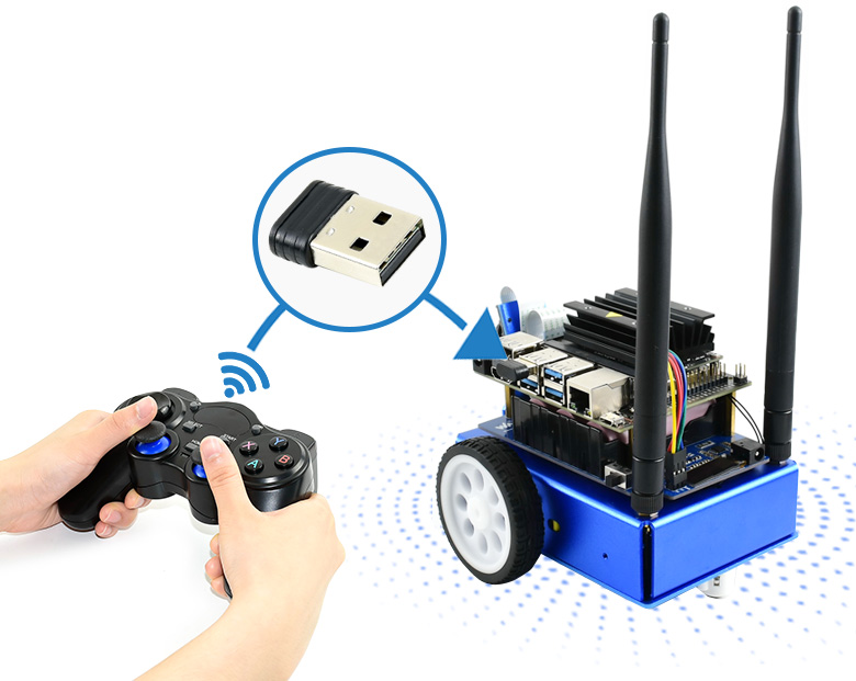
  5. Setup your Joystick, following these instructions. (update: see TCIII comment below for updated instructions) I used a PS4 controller (see TCIII’s comment below if you’re using an Xbox controller). Note that you’ll have to pair it via Bluetooth with the Nano. I did that in the Nano’s desktop interface by selecting the Bluetooth icon and adding the controller as a Bluetooth device when it was in pairing mode. The instructions say to set the driver to start at boot by editing the rc.local file, but you may find that the Nano doesn’t already have one. No worries, just create it from scratch and add the necessary line like this:
sudo nano /etc/rc.local
paste /home/pi/env/bin/ds4drv --led 00ff00 into the file. Save and exit.  

If you’re using a PS3 controller, in manage.py change this line to say this:

cont_class = PS3JoystickController 

Set bus num to 1 in myconfig.py:

 PCA9685_I2C_BUSNUM = 1

After you’ve done that, set up the directory with this:

 donkey createcar --path ~/follow --template path_follower 

Running:

 cd ~/follow 
 python3 manage.py drive 

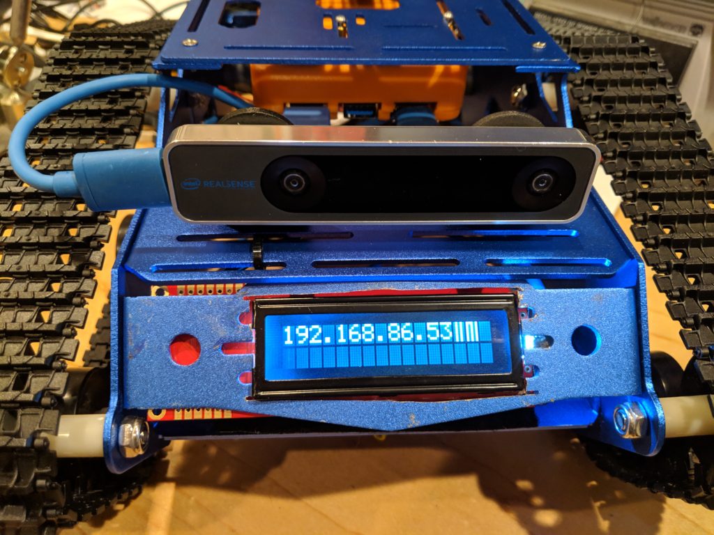
Once it’s running, open a browser on your laptop and enter this in the URL bar: http://<your nano’s IP address>:8887

The rest of the instructions from Tawn’s repo:

  • When you drive, this will draw a red line for the path, a green circle for the robot location.
  • Mark a nice starting spot for your robot. Be sure to put it right back there each time you start.
  • Drive the car in some kind of loop. You see the red line show the path.
  • Hit X on the PS3/4 controller to save the path.
  • Put the bot back at the start spot.
  • Then hit the “select” button (on a PS3 controller) or “share” (on a PS4 controller) twice to go to pilot mode. This will start driving on the path. If you want it go faster or slower, change this line in the myconfig.py file: THROTTLE_FORWARD_PWM = 530
  • Check the bottom of myconfig.py for some settings to tweak. PID values, map offsets and scale. things like that. You might want to start by downloading and using the myconfig.py file from my repo, which has some known-good settings and is otherwise a good place to start.

Some tips:

When you start, the green dot will be in the top left corner of the box. You may prefer to have it in the center. If so, change PATH_OFFSET = (0, 0) in the myconfig.py file to PATH_OFFSET = (250, 250)

For a small course, you may find that the path is too small to see well. In that case, change PATH_SCALE = 5.0 to PATH_SCALE = 10.0 (or more, if necessary)

If you’re not seeing the red line, that means that a path file has already been written. Delete “donkey_path.pkl” (rm donkey_path.pkl) and the red line should show up

It defaults to recording a path point every 0.3 meters. If you want it to be smoother, you can change to a smaller number in myconfig.py with this line: PATH_MIN_DIST = 0.3

Meet Ross Robinson, the Defender of Humanity

As you know, the DIY Robocars races are partly about beating other cars, but they’re also about beating puny humans. And we’re getting pretty close!

But see that yellow line at the bottom representing the “fastest human time”? That time was set almost a year ago by a human who…let’s put this gently…may not have been the fastest RC driver on the planet. Or possibly even in the room.

So now it’s time to give the humans a chance to defend themselves better before those red and blue lines cross the yellow and our species is rendered unnecessary.

Enter Ross Robinson (above)! By day he’s a robot wrangler at 3DR (as am I), but unlike the rest of us geeks, he’s pretty good at driving a car. And he not only has a fast one, but it’s set up with a camera for First Person View driving, so his view of the track will be exactly the same as the autonomous cars!

So, starting with the Sept 21st event, the last race of the day will be the fastest robot car vs the fastest human present. The first one will be Ross.

No pressure, Ross, but the fate of humanity lies in your hands

Adventures with the Nvidia JetBot and JetRacer

Along with the fantastic $99 Jetson Nano, Nvidia has released two DIY car kit guides to use the Nano for real-world robotics. I’ve built and got them both working, so this is a quick overview of the two and some tips and tricks. (There’s also a good hands-on of the Jetbot at ExtremeTech, which is worth reading, too)

The Jetbot is designed to use computer vision and AI to navigate small areas slowly, such as the Lego-scale roads shown here, to demonstrate basic self-driving car techniques.

The parts are available in various options:

  • Order them all separately from this list (about $150)
  • Kit from Adafruit ($34.95, requires a Jetson Nano, the 3D printed parts, camera, wifi, battery and a few other parts from the list above)
  • From 3rd parties with everything but the Nano for $230
  • Just the 3D printed parts ($35), if you don’t have your own 3D printer
  • Sparkfun is also planning their own kit ($274), which looks a little too cobbled together for my taste, so that wouldn’t be my first choice

Waveshare also has its own 3rd-party variations of the Jetbot, which improves on the original with a metal chassis and integrated electronics (see below). This seem to be the best deal, at $219 INCLUDING a Jetson nano, but I haven’t tried it myself. Update: now I have and it’s terrific. Short review here, but here’s it next to my DIY version:

However, the Nvidia team has tried it and they like it a lot, especially with its integrated battery charging, so that seems like the best bet if you don’t want to get and make the parts yourself.

What can it do?

The basic examples are collision avoidance and object following, both of which use the Nano’s deep learning abilities and Jupyter Python interface for training well. Here’s one example of it working:

A new example, which you’ll find on the on-board Jupyter notebooks but not the wiki yet, is road following. I trained it on my patio track, which is meant for larger vehicles that can roll over the tile bumps, but despite what must have seemed like pretty rough terrain for this little bot, it made it around the track pretty well:

More to the point, this is a general purpose AI platform. Anything that can run on a Jetson can run on this (within the limits of the Nano’s processing power): TensorFlow, Keras, OpenCV, etc. It’s running a flavor of Ubuntu Linux, so DonkeyCar works, and you can even train locally (as opposed to in the cloud)! The only limits are the small and slow car…

Enter JetRacer!

JetRacer is more than just JetBot on a faster RC chassis. The Nvidia team also increased the speed of the software processes, including increasing the camera frame rate and optimizing TensorRT to handle the speed of the vehicle.

It’s also got a simplified training scheme to gather data faster. Like JetBot, it uses “supervised learning”, which is to say that you, as the human, put the car on the track and point to where it should drive in various different positions. You do that about 50 times, train for 5 minutes, and then it can drive itself. On JetBot, this involves using a joystick to point to a path. On JetRacer, you just click on the spot it should drive to (no joystick required).

Now, you’ve got a vehicle that can compete in a DIY Robocars race. This isn’t a good example of a proper track (my patio isn’t big enough) but it will give you a sense of how it compares to JetBot, above:

Here it is training on the beginners track at the proper DIY Robocars track at CircuitLaunch:

The standard JetRacer chassis is a 1/18th-scale Latrax model, which has a 7″ wheelbase. That’s plenty fast for me (and it qualifies for the “Stock” DIY Robocars category), but if you want to go even faster, they support a 1/10th scale version based on the Tamya chassis, which I think can compete with the fastest cars we have.

A final note on the Jupyter notebooks Nvidia supplies for road training. They’re good, but confusing. The process goes like this:

  1. Gather data by recording 50 images or so, with human suggestions on where to steer for each
  2. Train with those images
  3. Check your trained model with some live video from the car on the track, to see if the blue dot (“steering target”) is pointing to the right place to drive to
  4. Run it live on the car, tuning various parameters for the best performance

Right now, those four steps are combined into two Jupyter notebooks, which is both confusing and tends to bog each down with unnecessary processes running in the background. My advice to the Nividia team would be to split them up a bit more. #1&#2 above should be one notebook. #3 should be another, and #4 should also be a stand-alone, with interactive sliders that work in real-time to adjust driving parameters, exactly as JetBot does.

So, in summary, JetBot is easy to use but slow. JetRacer is fast, but hard to use. Memo to Nvida: Combine the best of the two and you’ll have a winner!

First impressions of the new Zumi robot car

First of all, it’s ADORABLE! So small, it can fit in the palm of your hand, but has a RaspberryPi ZeroW, and Arduino, a screen, camera, loads of sensors and LEDs all inside.

Zumi started as a Kickstarter project and just shipped to first backers (I was one) last week. You can now buy it directly from its creators, Robolink, for $139. Details are here.

My first impressions were very positive, despite the usual first-batch problems with Kickstarter projects (a few missing bits in the kit and some instructions that aren’t quite accurate). It was easy to put together and once I fixed a boneheaded mistake (if you plug in the screen connector backwards, the car won’t boot at all — yikes), it booted up fine and coached me through the process of connecting via wifi and updating its firmware.

So what can it do? The initial Kickstarter pitch focused a lot on computer vision and AI, but it’s clear that many of those videos were done on beefier computers than the RaspberryPi Zero in Zumi. The current package is more limited, with no real machine learning at all.

Nevertheless, the initial lessons are a lot of fun and show the solid Python functions Robolink has shipped with Zumi. Examples start with how to use a Jupyter notebook, and then move to sensors (IR distance/obstacle, gyro and accelerometer), LEDs and the buzzer and of course motion. Although Zumi’s motors don’t have encoders, it uses the gyro to go straight and turn by set amounts, which works well.

Once you get to computer vision, the limits of the RaspberryPi Zero, hobbled by the overhead of the Jupyter server and wifi streaming, show up. Lessons in object tracking, face and smile spotting and color spotting all suffer from terrible lag and several can not finish at all.

Although Robolink promises more is coming with updates, it’s hard to see how they can squeeze much more about RPi Zero using Jupyter. Although Jupyter is a great way to combine documentation, code and graphical output on one screen, it’s really designed to run on faster computers and slows to a crawl on Zumi if the camera is used. Robolink intends to release a different IDE in the future, perhaps one more like their Blockly interface, and that may work faster.

Once Robolink fixes the performance issues (perhaps by switching out Jupyter for a faster IDE) I think computer vision, including lane following and object detection, should be doable. Basic machine learning (with models trained in the cloud and only run locally) should also be possible. And who knows — maybe the Rasperry Pi Foundation will release a faster RPZero someday?

But for now, Zumi is really nicely designed and super-cute robot car at a reasonable price with a lot of room to grow.

Experiments with new all-in-one motor/motor controller/encoder

DF Robot has an interesting new robotics motor ($19), which has both the motor controller and the encoder integrated into the body. That means that you can drive it straight from an Arduino, with no separate motor controller required. That’s pretty cool and leads the way to very simple rover setups.

The motor is 12v (good choice for a 3-cell, 11.1v lipo battery), geared to max 159 rpm. It’s smaller than the usual robot motors, but has enough power for a small rover.

Because it’s so well integrated with controller and encoder, it’s a good way to demonstrate proper PID motor control. So here’s a demo! The code is here:

Connect it to an Arduino like this (the wire colors will probably be different; pay them no mind. Just keep the red and black right and connect the others in the following order). Important: you must also connect the Arduino ground to the 12v power supply ground as shown):

Full details are in the DF Robot wiki

Now try it with a PID controller, which will maintain a desired RPM within a reasonable range (80-140 rpm). Here’s some Arduino code that will do that.

Try playing around with the Kp (proportional), Ki (integral) and Kd (derivative) terms in this code and see what happens when you enter a different speed (80, 100, 120, etc). With the stock settings below, the Ki term will slowly build up so the RPMs approach the desired speed. A higher Kp term will speed up that convergence, but too high will overshoot. Here’s a short video that gives the basics, but the key points is that it uses feedback.

You want the speed of the motor to be a certain value, but just commanding it to go to a certain power doesn’t mean that it will get to exactly the desired speed (because of variation in battery voltage, etc). So rather than just sending a command and hoping for the best, you measure the actual speed the motor is turning with the encoder. Then just keep changing the motor control inputs until the motor speed output is close to the desired one — that’s what a PID controller does. All the various settings (P. I. D.) are just to tune it so it does that well.

// Make sure you've added the official Arduino PID library to your libraries
 // https://playground.arduino.cc/Code/PIDLibrary/
 include 
 int i = 0;
 int rpm;
 unsigned long time = 0;
 bool direction = HIGH;
 int speed;
 double Setpoint, Input, Output;  // Setpoint is going to be the desired speed. Input will be encoder reading. Output will be motor command
 double Kp = 0.5; 
 double Ki = 3;
 double Kd = 0;
 //Specify the links and initial tuning parameters
 PID myPID(&Input, &Output, &Setpoint,Kp,Ki,Kd, REVERSE);
 void setup() {
   Serial.begin(115200);
   pinMode(10, OUTPUT); //PWM PIN 10  with PWM wire
   pinMode(11, OUTPUT);//direction control PIN 11 with direction wire
   digitalWrite(10, direction);
   Setpoint = 100;
   Input = 100;
   myPID.SetMode(AUTOMATIC);
 } 
 void loop() {
   if (Serial.available())  {
     speed = Serial.parseInt();
     speed = 255 - speed;
     delay(200); 
   }
   for(int j = 0;j<8;j++)  {     i += pulseIn(9, HIGH, 500000);         //SIGNAL OUTPUT PIN 9 with  white line,cycle = 2i,1s = 1000000us,Signal cycle pulse number:272   }   i = i >> 3;
   rpm = 111111 / i;   //speed   r/min  (601000000/(4562i))
   i = 0;
 //  Serial.print(rpm);                      
 //  Serial.println("  r/min");
 Setpoint = 255-speed;
   Input = rpm;
   myPID.Compute();                       // calculate the right motor control to make rpm equal desired speed
   if (Output > 220) {Output = 220;}
   if (Output < 20) {Output = 20;}
   Serial.print("Setpoint, Input, Output: ");
   Serial.print(Setpoint);
   Serial.print("  ");
   Serial.print(Input);
   Serial.print("  ");
   Serial.println(Output);
   analogWrite(11, Output);
 }

If you enter a desired RPM between 80 and 130 in the Arduino Serial Terminal it will try to hit that number. Output should look something like this (“Setpoint” is PID-talk for “desired speed”. “Input” is the reported speed from the motor encoder. “Output” is the motor control signal [0-255] that the code sends the motor):

Official Oakland Race Rules (2019 edition)

Now that the DIY Robocars quarterly races in Oakland have gotten big and the cars fast, it’s time to evolve the rules to reflect our learnings over the past two years.

As of the Sept 21 2019 race, these are the new rules:

There are two tracks, one for beginners and a main one for returning racers:

  • There are 12″ orange cones on the inside of every curve, as shown above.
  • There will be one “obstacle cone” placed at a random location (changed with every race) inside the track.
  • The Beginners Track has the same shape, but is about 25% smaller

If this is your first race or your car’s first race, you must start on the Beginners Track. There will be one judge on that track to schedule official runs. If you can successfully complete a lap in under 40 seconds, you may advance to the Main Track and place your team name on the lineup board (example from a recent race shown below).

Main Track Rules:

Cars:

  • Cars must start with a single binary interaction. This could be a button on the car, on a controller, a key on a keyboard or equivalent. No other intervention can happen until after the race is over; otherwise the car gets a “did not finish” (DNF). An emergency stop button is recommended but not required. Deadman’s switch is also acceptable where button is pushed and held for the duration of the race.
  • There are no rules governing where the computing needs to take place.  Cars may have onboard computing, trackside computing or leverage remote or cloud resources.  
  • GPS and other similar positioning systems are not allowed except for specified outdoor races. 
  • The desire is that this is an open source league and that all designs are put on github and are readily copyable after the conclusion of every race.  If you are prevented from open-sourcing designs or prefer not to, there is no obligation to do so.

There are two categories of racers: Stock and Unlimited

1) Stock:

  • This includes all the standard platforms: DonkeyCar, JetRacer, DeepRacer as well as any custom vehicles that satisfy the below criteria
  • Cars are 1/16th scale or smaller: No more than a 7.5″ (190mm) wheelbase, axle to axle.
  • Cost no more than $400 all told (car, computer, sensors, etc)
  • Batteries must be firmly attached with velcro or other straps so they can’t come loose during the race

2) Unlimited:

  • This is for cars larger and/or more expensive than Stock
  • Cars may be up to two feet long and may weigh up to 10lbs
  • No limit on cost (although we do encourage DIY economics — if you’ve spent $10,000 on a Lidar sensor, this may not be the right event for you. Not only is it out of reach for others to follow, but in the obligatory Demolition Derby at the end it may very well get damaged)
  • Batteries must be firmly attached with velcro or other straps so they can’t come loose during the race

Races:

  • There are three heats, followed by a “ladder” race-off of the top six cars, paired by closest times, ending with a final race between the top two cars for the winning trophy (not actually a trophy!).
  • All races will be “wheel-to-wheel” with two cars on the track at the same time
  • Every car will have at least three opportunities to race. Only those in the top six will move on to the ladder.
  • The first heat pairings are random, within the class they have entered. After that, the second and third heat pairings are based on matching closest times within their class in the first heat.
  • Racers may choose to agree on track starting position (inside or outside lane). If they do not agree, the judge will flip a coin to decide.
  • The final race is an all-cars Demolition Derby. If you brought a car, even if it didn’t qualify for the Main Track or even if it doesn’t even work autonomously, you will race. There will be crashes. It will be fun. It’s the best 30 seconds of mayhem of the day.

Scoring:

  • Each heat is three laps. Both the first lap and the three-lap times will be recorded for each car, but only the first-lap time will determine ranking for the next heat (or ladder position)
  • Passing any “curve cone” on the inside is immediate disqualification for that heat
  • There is no penalty for going outside the white lines, as long as you don’t violate the cone rule above
  • The random “obstacle cone” may be passed on either side. Hitting the obstacle cone imposes a two-second penalty
  • Touching any other cone is a one-second penalty

Adding challenges to DIY Robocars tracks

Now that our computer and software platforms have improved to the point that we’re reaching the maximum physical speed of cars on regular “kidney-shaped” track without resorting to crazy tires and motors, it’s time to slow things by adding more challenge on the CV/AI side.

There are three standard ways to do this:

1) Always race with at least one other car (“wheel-to-wheel” racing). These “moving obstacles” introduce both randomness as well as the need for smart race tactics to win. Those include:

  • Spotting other cars
  • Deciding to pass on the inside or outside
  • Picking the right time to pass (straightaway, before a curve, after a curve)
  • Using AprilTags or other standard computer-readable markers on the back of each car to make them easier to identify

2: Place a cone or other obstacle in the track at some random location before each race. This introduces the following challenges:

  • It breaks naive “cone trackers” that assume that cones are stationary and always at the outside of the track
  • Requires car to differentiate between “outside” cones (which mark the outside of the curves and must always be passed inside and not touched) and “inside” cones (which can be passed on either side)
  • Requires cars to do more than just track the road lines

3: Static obstacles, such as gates, ramps or simulated pedestrians (like the above, from the Sparkfun AVC 2018). This can introduce a number of unique challenges and fun scoring opportunities:

  • Having to differentiate by kind of obstacle, such as “pass to right of blue cone but to left of red cone”, or “some blue ramps add points if jumped, but others have spikes and will stop your car”.
  • Offer extra points (or subtracted seconds) if the car successfully passes through a hoop or between two markers in tight bottleneck
  • More advanced path-finding and decision-making, such as “stop for two seconds if a stop sign is detected” or “stop for detected pedestrians but just steer away from other obstacles”

Starting with the September 21 race in Oakland we’ll do at least #1 and #2; #3 may come later.

How to display your Linux computer’s IP address on a LCD (and a few ways not to)

In a “headless” configuration (no screen or keyboard) such as typical in Raspberry Pi or other embedded computers in small robocars, one of the biggest hassles is figuring out what IP address the computer has been assigned over Wifi on the network you’re connecting to. There are some tools, such as Adafruit’s PiFinder, that will search a network to find connected RPis, but in my experience on large corporate networks they usually fail.

A better way is for the computer to display its own IP address once it boots and connects. But on small cars you don’t have room for a HDMI monitor, so you’ve got to connect a small LCD or OLED screen, such as these I2C or SPI displays from Adafruit or just a serial display like these. That’s easy enough to hook up, but how do you get the computer to automatically display on these displays its IP address when it boots up?

Google around and you will find many suggestions for autorunning programs at boot, especially for Raspberry Pi, which are a constant source of headless headaches. The problem with most of these is that they don’t work anymore. The main reason is that Debian (and, by extension, Raspian, the Linux varient that RPi runs) has changed some key functions in recent releases, breaking old methods. So, for example, putting the startup script in rc.local doesn’t work in current distros. Nor does putting it in etc/network/interfaces. All of these are ignored in the latest Debian/Raspian/Ubuntu releases.

Even worse, the hard part about this particular startup problem is that you can’t just run the program at startup, but you have to wait until it connects to a network and *then* display the IP address.

The solution is a method that uses the Linux “cron” function, which still works in current distros. Here’s what to do, using a serial LCD screen connected via USB on ttyUSB0:

  1. Edit your startup cron file by entering “sudo crontab -e” from the command line.
  2. That will ask you for an editor. Pick nano. In nano, type ”
    @reboot /home/[your username]/startup.sh”, then press control-o and then control-x to save and exit. (To explain that line we just entered, it means “at reboot, run the startup script “startup.sh” in the user’s home directory)
  3. Now go to your home directory and type “sudo nano startup.sh”, which will create that file
  4. If you’re using a serial LCD as shown above, type or paste this into that startup script, and then again pressing control-o, control-x to save and exit:
#!/bin/bash
sleep 10
ip addr | grep 'state UP' -A2 | tail -n1 | awk -F'[/ ]+' '{print $3}' > /dev/ttyUSB0
  • 5. The above line waits for 10 seconds for the network connection, then uses the “ip addr” command to get the IP address. It searches for the network connections that are working (“up”) and returns the IP address, piped to the serial port at ttyUSB0
  • 6. Now make sure sure startup.sh is executable by typing this in the command line:
sudo chmod +x startup.sh

Now it should start at next boot, wait 10 seconds, and then send the assigned IP address to a serial LCD screen.

There are better ways to do this, including a script that keeps running through a loop until “state UP” returns true, thus avoiding the fragile delay function, which might fail if the network connection hasn’t been reached in 10 seconds. But this works for me.

BTW, if you’re using an I2C or SPI screen, you’ll be better off calling a Python program that has a library to control it, rather than the simple serial LCD I used. But that’s more complicated, so I’ll leave it to another day.