Starting with the March 7 Circuit Launch event, we’re going to be adding an outdoors track for cars using GPS or otherwise wanting more of a challenge than the indoor track. Although the outdoor track will be open all day (starting at 10:00am) of the event, the formal competition on that track will only begin after the indoor event has concluded, at 3:00pm, and conclude at 5:00pm.
The below shows roughly where the track will be, in the parking lot at the side of Circuit Launch. There will be white tape marking the outside and inside of the track and cones placed at the corners. More details on the track and challenges (random cone obstacles, etc), will be announced on the day of the event.
To aid in GPS-guided navigation, we will have two RTK GPS base stations broadcasting. One is an Emlid Reach RS+, the other is a Swiftnav Piksi2. If you want to use either of these, you car must have a compatible “rover” GPS mounted on it. We recommend the Emlid Reach M+ (it can also work without a base station)
Regular GPS units will work too, of course, but will not be as precise as RTK GPS. But if that’s all you have, bring it and see how well it does!
BTW, if you’ve never tried GPS-guided autonomous cars, we recommend you start with the ArduRover project, which has been used successfully for years at the Sparkfun Autonomous Vehicle Competition (RIP), and uses the same Pixhawk autopilot hardware as many drones.
One of the most useful sensors to add to an autonomous car (after the camera) is an encoder. This “closes the loop” of motor control, giving you feedback on what actually happens when you send a speed command to the motor (the speed the motor actually turns can depend on a lot of things, from the battery voltage to the increased load on the motor going uphill, etc).
In a perfect world we’d have an encoder on each wheel, showing the actual rotation of each tire, which, slippage aside, should perfectly correlated to speed and distance traveled. But it’s too hard to retrofit most RC cars to add encoders on each wheel, so this post will show you how to do it the easy way, with a single encoder on the motor. That will at least give you motor speed feedback and since that shaft is distributed to all the wheels, it averages out quite close to car speed and distance.
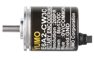
We’re going to be using “quadrature” encoders, which know the difference between forwards and backwards rotation and are easily read by a simple microcontroller. I’ll offer two alternatives that work the same, although one is cheaper (albeit larger) than the other.
I won’t be going into how to use this encoder information in your robocar, since it depends a lot on which software stack you’re using (Donkeycar, Jetracer, etc). That will wait for the next post. This one is just for the mechanical and electrical installation.
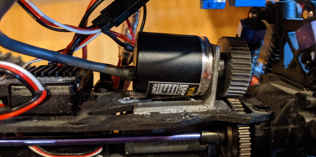
As you can see from the photo above, the standard Donkey chassis (the Exceed Magnet) has space to put the encoder above the motor where there is a large drive gear that is easily accessible.
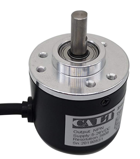
Your choices are pretty simple. The cheaper encoder below is bigger (38mm diameter) and weighs a bit more. The more expensive one is smaller (25mm diameter) and proportionately lighter. My picture above shows the smaller one, which is a slightly neater installation, but if you want to save a bit of money the larger one works just as well.
You’ll also want a microcontroller to read the encoder data, which is easier to do on something like an Arduino than it is on a Linux computer like a RaspberryPi or Jetson Nano. I use a Teensy LC for that, which is faster than a stock Arduino and nicely small. You can buy that from many places, such as PJRC ($11.65) or Amazon ($15.26). But any Arduino-compatible microcontroller will do, such as the Adafruit Feather series or an Arduino Mini.
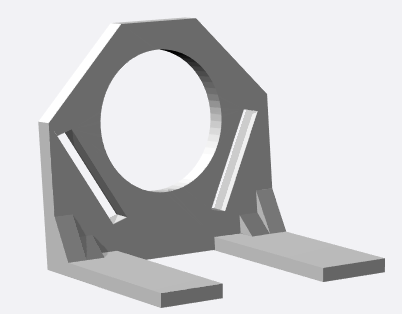
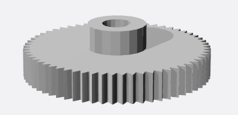
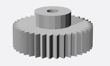
If you have a 3D printer, you can download the files for the mount and gear below. Or if you don’t, you can order them from the same link.
Cost
Encoder
Mount
Gear
$15.99 (plus $10 for 3D printing if you don’t have your own printer)
Just screw the encoder on the mount, press the gear on to the shaft, and position the encoder as shown above so that the gear seats nicely on the motor gear and turns with it, without slipping. You can glue the mount on the car chassis shelf when you have the right position.
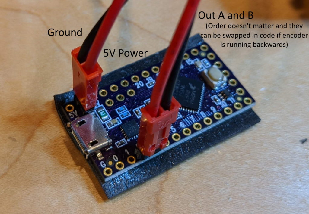
Once you have the encoder in place, solder pins on the the Teensy board in the pins shown below (USB V+ and Gnd and Pins 2 and 3), cut the encoder wires to the desired length and splice female connector of any sort to them as shown. On the smaller encoder, there is a fifth wire (orange, called “Output Z”) that can be cut off and ignored.
On the Teensy (or any Arduino), you can run the standard Arduino encoder library to test the encoders. Just search for it in the Arduino Library Manager and install it. From the Arduino Examples menu, select the Encoder/Basic example and edit it to reflect the pins you’re actually using:
Encoder myEnc(2, 3);
Now you’re up and running! You should be able to open the Serial Terminal (9600 baud) in the Arduino IDE and see the values streaming as you turn the encoder. To use this with your robocar code, you’ll want to plug the Teensy/Arduino into your main car computer’s USB port with a short cable, where it should show us as a serial port. You can can then read the encoder values over serial and use them as you see fit.
More details on how to do that with the next post.
In the past year there’s been an explosion of good, cheap depth sensors, from low-cost Lidars to “depth cameras” with stereo vision and laser projection. It’s now easy to augment or even replace computer vision with depth sensing in DIY robocars, just like most full-size self-driving cars do. Intel has been leading a lot of this work with its great Realsense series of depth sensing and tracking cameras, which are under $200 and have a solid SDK and often built-in processing. This post is the latest in my tutorials in using them (a previous post on using the Realsense T265 tracking camera is here).
One of the ways to compare depth sensing cameras with Lidar (2D or 2.5D) is to use them to navigate a maze. There are lots of ways to navigate mazes, including very simple depth sensors such as an array of ultrasonic (sonar) or 1D laser range sensors (“time of flight”), but the common factor between a Lidar unit and a depth sensing camera is that they do more than those 1D sensors: they both return an array of pixels or points with depth information across a sweep of area around the vehicle.
The difference between these two kinds of sensors is that a spinning Lidar unit can potentially show those points around a full 360-degree disc. A depth camera, on the other hand, can typically can only see a rectangular area forwards like a solid state Lidar, with a horizontal spread of around 90 degrees. Unlike most solid state Lidars, however, a depth camera typically has has a much wider vertical spread (also around 90 degrees).
Camera tend to have shorter range than Lidar (10m max, compared to 20-30m max for low-cost Lidar) and lose precision the further they are from an object. On the other hand, depth camera are much higher resolution (a million points per second for a camera vs about 10,000 for a low-cost Lidar).
Cameras are also much cheaper: $180 for the RealSense 435 versus around $840 for the cheapest solid state Lidar, a Benewake CE30-A.
The purpose of this experiment was to see whether the Realsense Depth Camera could do as a well as a laser. Spoiler: it can! (see below)
A note about the computer I used for this, which was a Raspberry Pi 3. It doesn’t have enough power to really take advantage of the high speed and large data return from the Realsense sensors. However, I used it because I wanted to use the new Sphero RVR as the chassis, since it does a nice job of making all the motor driver and heading control simple and automatic, thanks to an internal gyroscope and PID-driven motor controller with encoders — you just tell it what direction to go and goes there, straight as an arrow.
The RVR can power your onboard computer with 5v via USB (it communicates with the computer via a separate serial cable). That limited me to computers that could be powered at 5v, which includes the Raspberry Pi series, Odroids and the Jetson Nano. However, there is also a low-cost x86 single-board computer (SBC) that Intel recommends, call the UP Board, and that runs on 5V, too. So if I was starting this again and I’d use that instead, since it should be able to install the Realsense SDK with a simple “sudo apt install” and “pip install”.
The second problem with the Rpi is that the Realsense SDK only works on Ubuntu (as well as Windows, although that wasn’t an option here). Although there is a version of Ubuntu (Ubuntu Mate) that works with the Raspberry Pi 3, support for the more powerful Raspberry Pi 4 is incomplete, and I couldn’t get Realsense to work on it. So Raspberry Pi 3 it was.
Compiling the Realsense SDK (librealsense) on the Rpi 3 can take a full day (unattended, thankfully) and you have to do it again every time Intel releases a new version, so that’s a bit of a hassle. So lesson learned: if you have an UP Board, use that. But if you happen to have a RPi 3, it will work, just more slowly.
Software
Enough of the hardware: let’s talk about the software! My approach to the maze-following task was to basically look at all the depth signatures in front of the car, with as wide a view as possible and a vertical “region of interest” (ROI) set as above the ground and not far above the height of the maze walls. I figure out which path has obstacles furthest away (ie, is most open) and head that way — basically go to where the path is clearest ahead. (This is mathematically the same as avoiding the areas where the obstacles are closest).
In my Python code, I do that the following way. Thirty times a second, the Realsense sensor sends me a depth map (640×480 pixels). To save processing time, I read every fifth pixel from left to right for each scan line within my vertical ROI (in this case from line 220 to 280), creating 128 “stacks”, each of which contains 60 vertical pixels, which is about 8,000 points in total. I then average the values within each stack and display them in a serial terminal in a crude character-based display like this (the smaller dots are the more distant obstacles, ie, the clear path ahead):
I then bin them in blocks of ten of these stacks, for a total of 13 blocks. Each block then gets an average and then I steer towards the block with the highest average (furthest distance). If I get stuck in a corner due to the relatively narrow field of view of the Realsense depth camera (“corner” = all visible directions have obstacles less than 0.75 meters away), I stop and rotate in 15-degree increments until I can see a clear path ahead.
It’s pretty simple but it works most of the time. That said, a simple 360-degree 2D lidar would do even better in this course, since it would be able to see the best open path at all times without having to stop and rotate. For that matter, a simple sonar “stay 10 cm from the right wall” method would work equally well in this idealized environment (but not in a real-world one). So perhaps a maze is not the best test of the Realsense sensors – a more open-world environment where they are used for obstacle detection and avoidance, not path following, would show off their advantages better.
Lessons learned:
Don’t use Raspberry Pis for Realsense sensors. Use Up boards or Jetson Nanos instead
Depth cameras are as good and way cheaper than solid state Lidar for short-range sensing
That said, 360-degree sensing is better than 90-degree sensing
The Sphero RVR platform is easy to use. It just works!