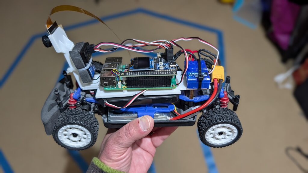
If you’re looking for a car that’s a bit smaller and easier to handle than the Exceed Magnet for Donkeycar, the 1:18th scale LaTrax Rally (https://amzn.to/45jWFDD) is great. Brushed motor, easy to add a third RC channel as an e-stop and fits the RP5 with the RC hat perfectly. You can use the RC it comes with, with no need for an I2C servo board or gamepad controller with limited range.
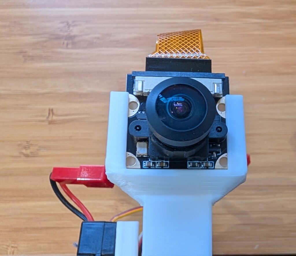
I designed a 3D-printable mount that fits the Pi and camera. Download it here.
If you want to add a third channel as an e-stop, you can follow the instructions here (scroll to bottom)
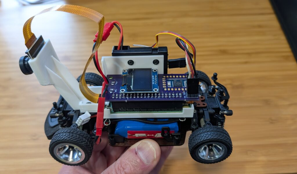
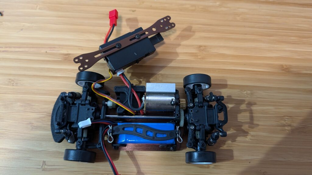
Yes, you can run Donkeycar, with a full end-to-end neural network driving autonomously, on tiny and cheap 1:28th scale cars! It’s perfect for indoors and small patios that don’t have room for bigger RC cars. Not only that, but you can use the RC controllers they come with. Here’s how to do it for less than $150:
First, you’ll need the car, a Raspberry Pi Zero 2 W and camera, a SD card (128GB or even 64GB is fine) and the Mini RC Hat. (It comes with the mount but if you have a 3D printer, you can also download this STL and print it yourself).
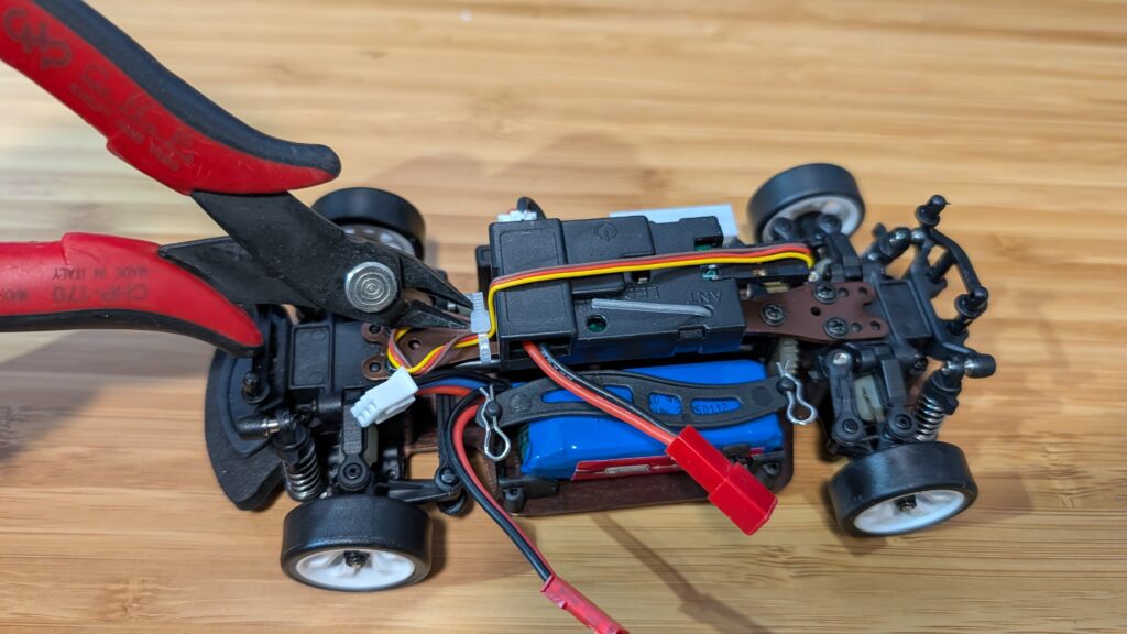
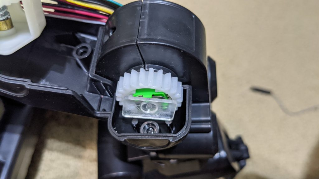
Once you have the car, take off the plastic body shell and remove the center beam as shown in the steps below. Save the screws since you’ll need them later.
First, clip off the zip tie holding in the steering servo cable
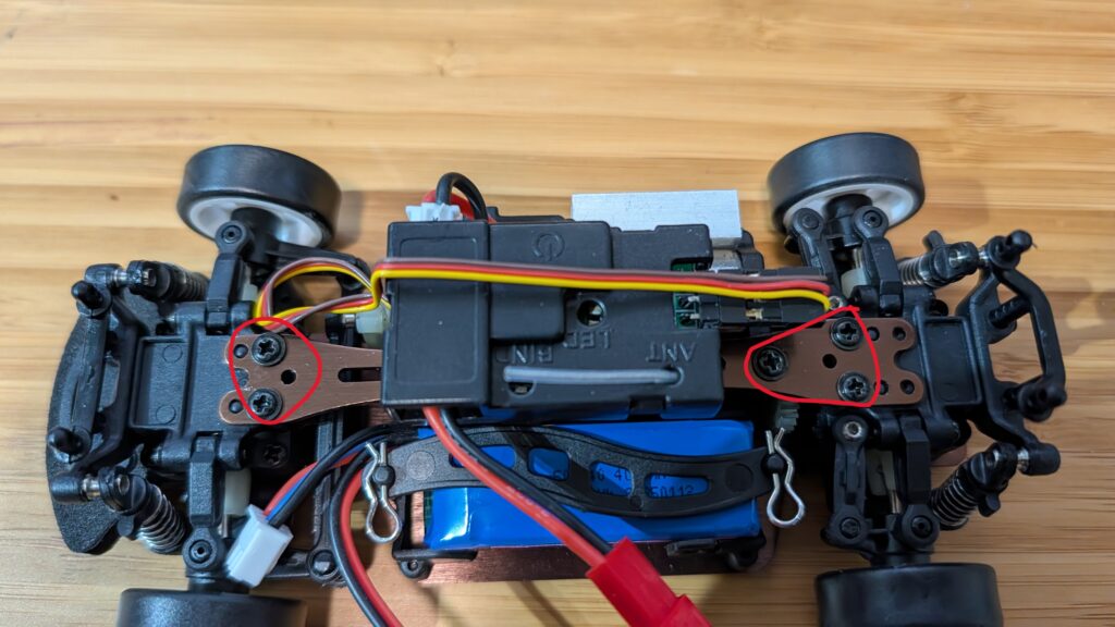
Then unscrew the screws circled in red below
Remove the center beam and unscrew the RC receiver
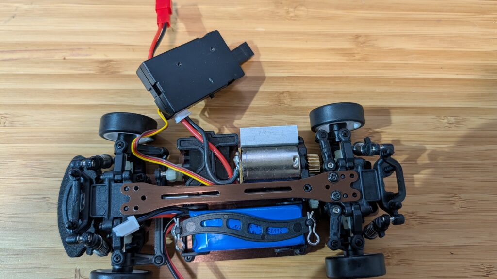
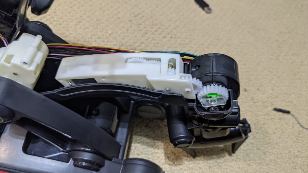
Replace the beam, just screwing in the two screws at the end. Make sure it’s seated all the way down on the little plastic posts
Screw in the Pi Zero mount using the remaining beam screws and screw in the RC receiver with the short screws that it used to mount to the beam
Mount the Pi Zero 2. You only need to screw it in with two screws, diagonally across from each other
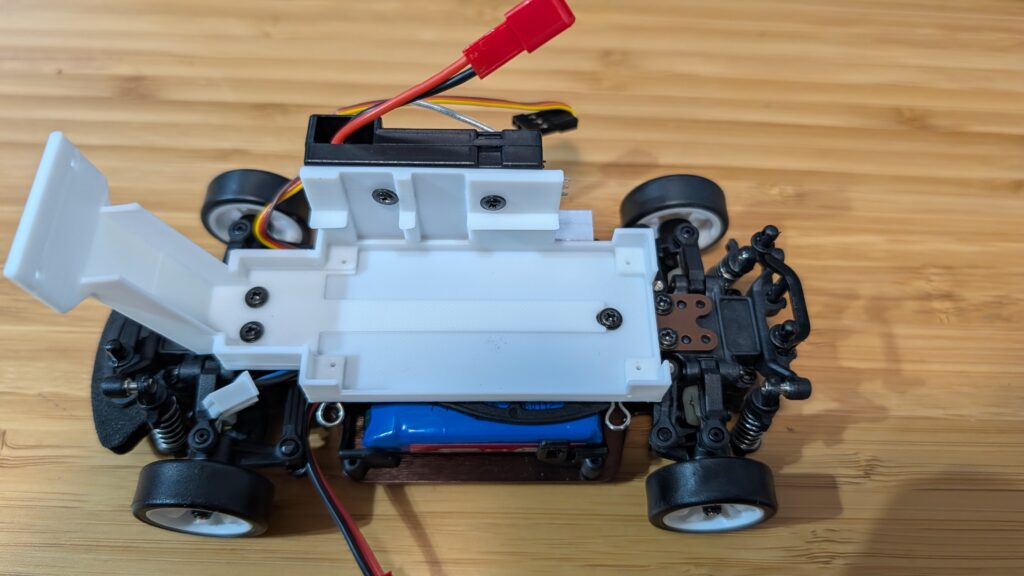
Place the camera in the mount slot, with the cable at the top.
For the software, we’ll be using an optimized version of Donkeycar that runs better on the Raspberry Pi Zero 2, which doesn’t have as much memory and compute as the Pi 5. Here’s how to load the software for that:
Step 1
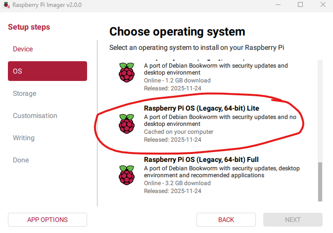
Using the Raspberry Pi Imager, select the Pi Zero 2 W as the target and for the OS, select Bookworm Lite 64 bit (Under “Raspberry Pi OS (other)”).
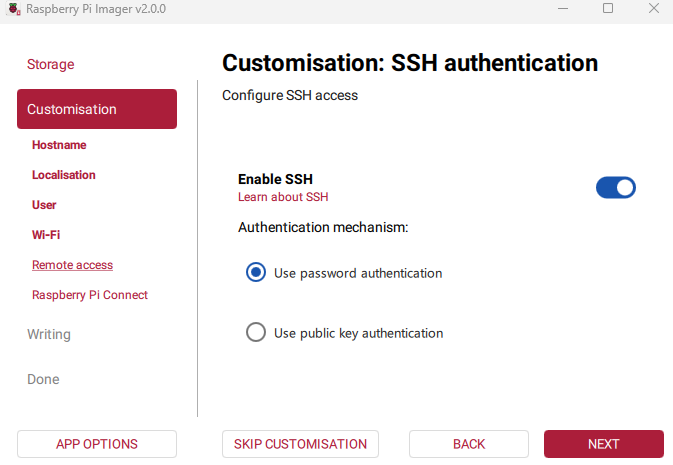
Fill out the rest of the options, including your desired name for the Pi (“donkeycar”) and your preferred username, password and Wifi details. Make sure you enable password SSH access, too:
Then write the image to card.
Step 2 Once it the SD card is done, insert it into the Pi Zero and power it on via the USB port. Once it boots up (green light stops flashing), which will take a minute or two the first time, SSH into via a terminal on your PC like this:
ssh <your username>@donkeycar.local
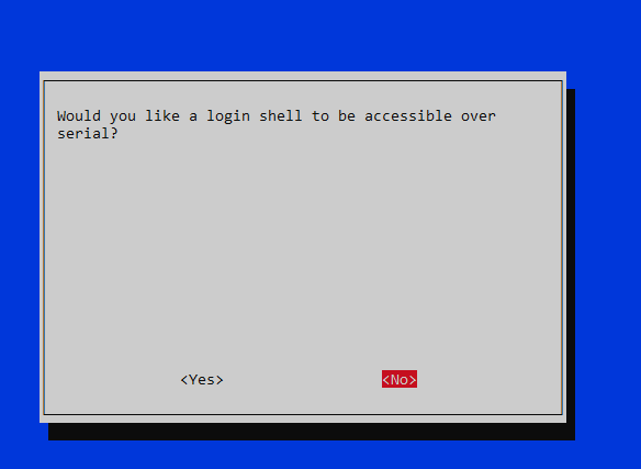
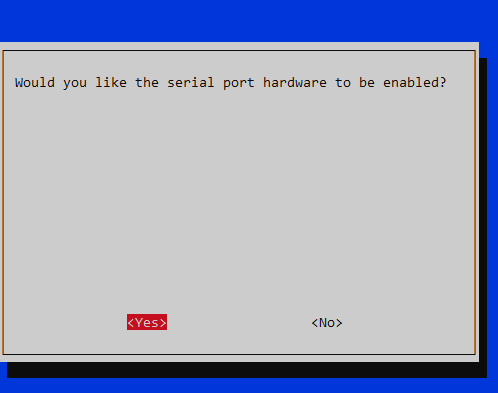
Once you’re in, go into raspi-config (“sudo raspi-config”) and make the following changes:
Under “Interface Options”, enable I2C and the hardware Serial Port (say “No” to the login shell being accessible over serial and “Yes” to the serial port hardware being enabled)
Under “Advanced Options” expand the filesystem
When you’re done, exit the utility and reboot.
When you log back in, enter this at the command line sudo nano /boot/firmware/config.txt In that file make two changes:
comment out “dtoverlay=vc4-kms-v3d” by putting a “#” in front of it
add this at bottom of file: “dtoverlay=disable-bt”
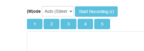
Finally, after you go through the regular recording of data with Donkeycar and then running a trained model, when you switch into auto mode with the web interface, choose “Auto (S)teer”. Because the 1:28th scale cars have an integrated RC receiver and motor controller, it’s too hard to extract the throttle signal and let Donkeycar manage it (lots of trace cutting and soldering would be required), so with these cars you control the throttle manually, while the AI controls the steering.
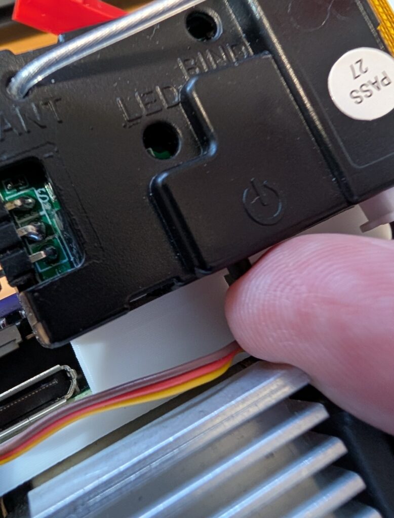
BTW, it’s not as obvious as it should be how to turn on the car. After you plug into the battery, you have to press this little button on the RC receiver, which will power on everything.
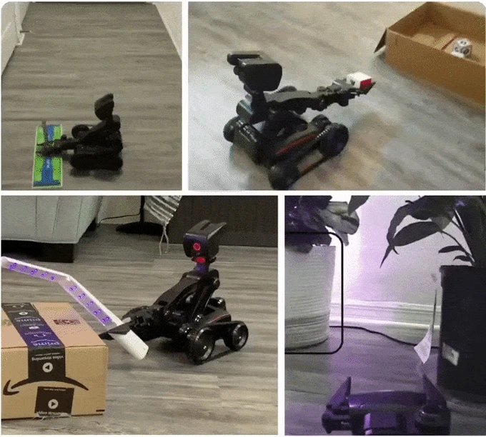
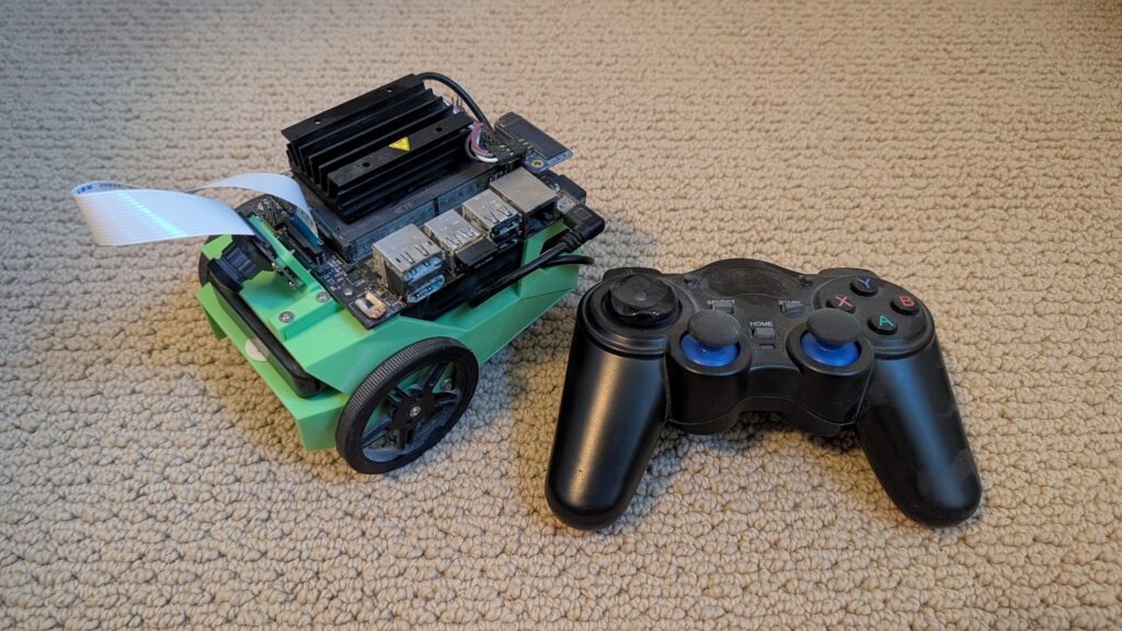
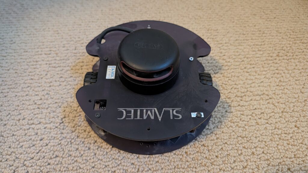
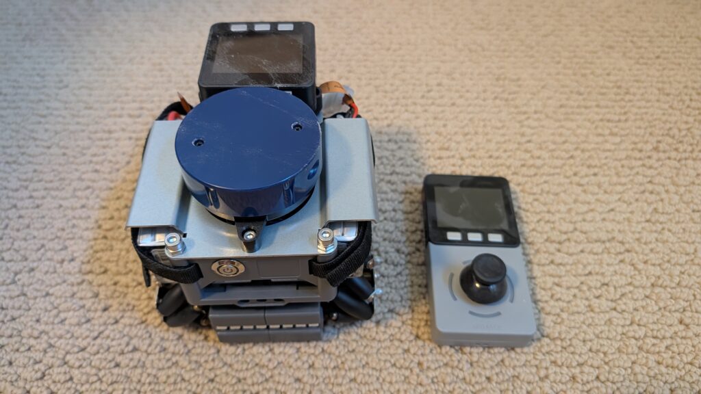
I’m clearing out my workshop and giving away a bunch of wheeled robots, all in good condition, that I won’t have time to use. These are free to a good home, but you must be willing to pick them up in the San Francisco Bay Area, either in East Bay or Palo Alto. DM me on Twitter/X or LinkedIn if you’d like something, and I’ll update the post as they go to show what’s still available.
Sadly, this is only about 30% of my collection. I may have a bit of a robot car addiction.
[now taken]
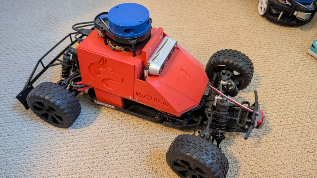
This is Musher.io, a very nice robot car with all the fixin’s from the University of Washington. It’s $1,000 worth of gear, from the Jetson Nano to the lidar, depth camera, VESC motor controller and fast and robust RC car chassis. ROS-based.
[now taken]
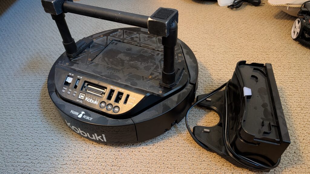
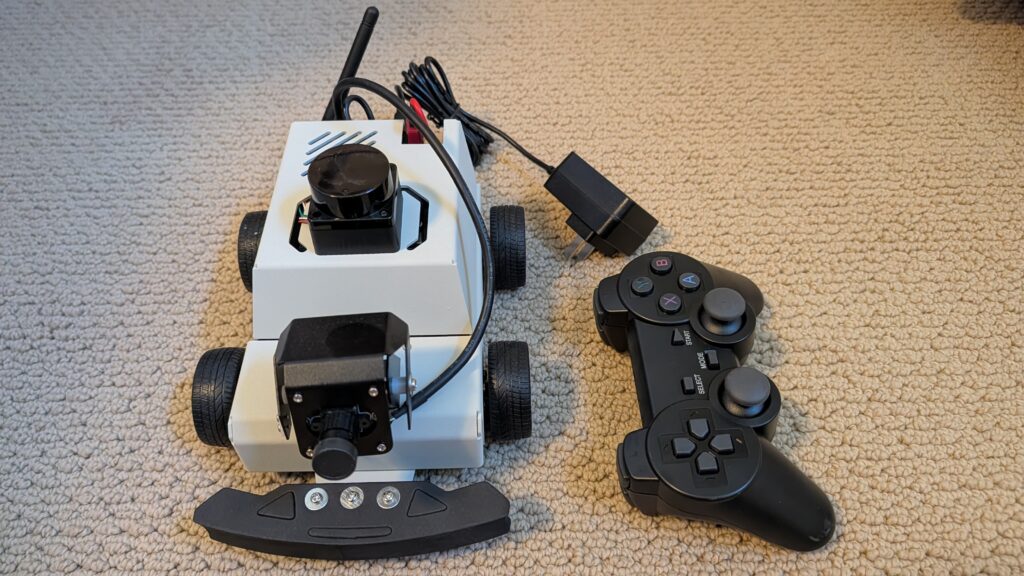
Yujin Kobuki robot platform. Like a Roomba Create, but optimized for robotics and adding sensors and actuators. Comes with recharging dock. $800 value.
[now taken]
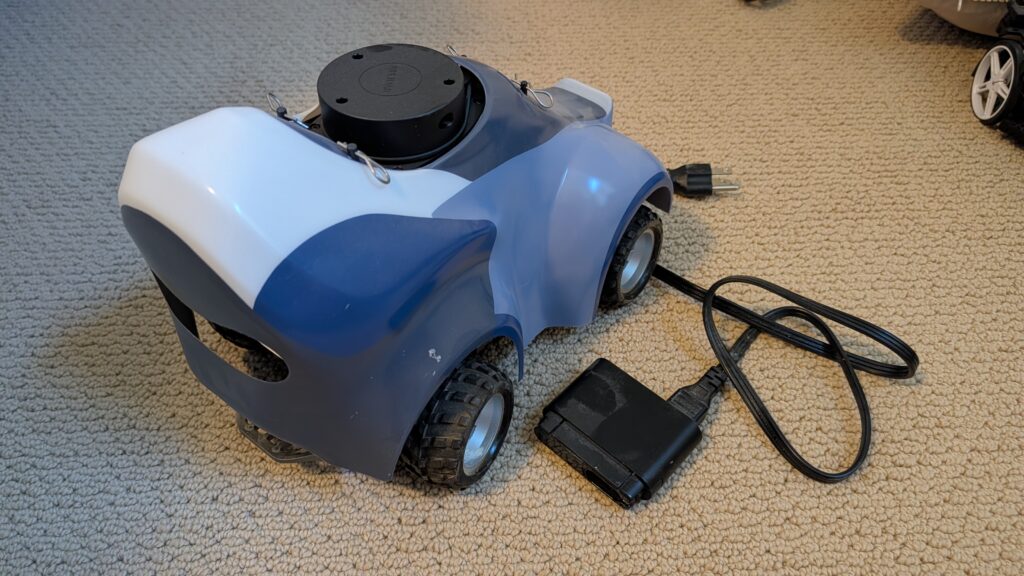
Amazon DeepRacer with stereo cameras and lidar. Was $800 new, including add-ons. Fully loaded!
[now taken]
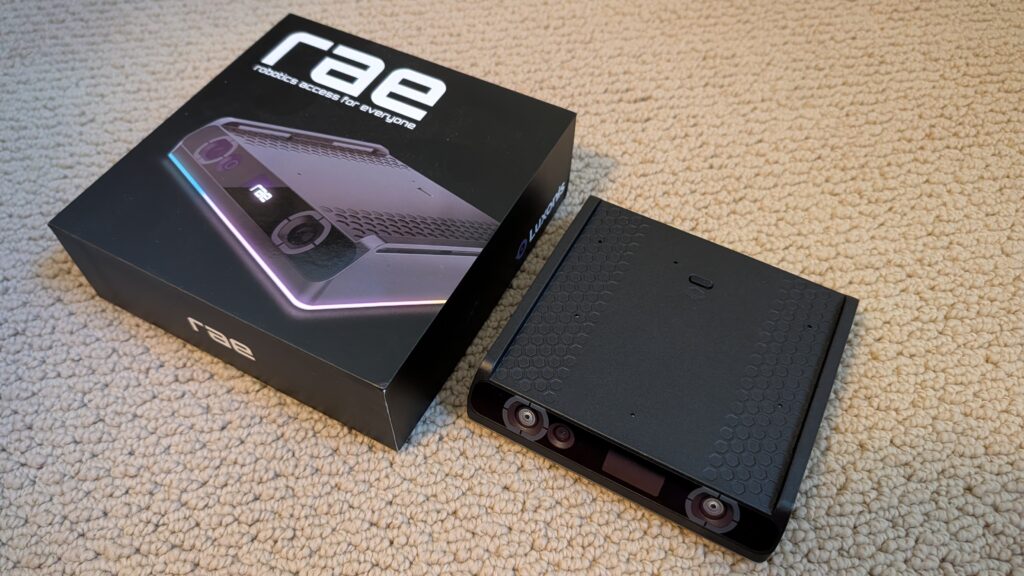
RAE robot from OpenCV with OAK depth camera. Still in the box.
[now taken] Zumi robot car. RaspberryPi-based. Can drive along a track and even obey stop signs and signals. Adorable!
[now taken] Microsoft Project Moab balancing platform. “Teach an AI brain to balance a ball in the center of a plate using a custom simulator and sample code.” Prototype, never released! Works
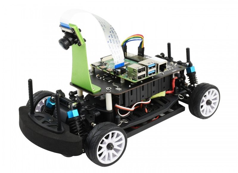
The $268 Waveshare PiRacer Pro (Waveshare, Amazon) is my favorite ready-to-run Donkeycar autonomous car, at least as far as the hardware goes. But it comes with badly outdated software, which is no longer supported by the Donkeycar project. So when you get one, the first thing you’re going to want to do is load the latest Donkeycar, which works great on that hardware.
Here are some tips on doing that.
First, install the latest RaspberryPi OS on the SD card, following these instructions.
Once you’ve done that, SSH into the Pi and after you’ve updated the OS (“sudo apt update", “sudo apt upgrade"), make sure you enable I2C using "sudo raspi-config").
Then you can you create the Donkeycar app by following these instructions.
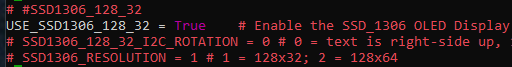
Before you can run Donkeycar, you need to customize some settings in the myconfig.py file in your mycar directory.
Enable the OLED screen by uncommenting this line and setting it to True (note that the OLED will only show text when you’re running Donkeycar, which you’ll do later when you’re ready to drive with “python manage.py drive“).
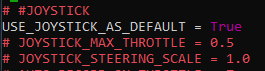
Enable the game controller that comes with the car by uncommenting and setting the Use Joystick as Default to True if is not already.
It will default to Xbox mode. To ensure that your gamepad is in Xbox mode, hold the Home button for 7 seconds after powering it on
That’s it! Your Waveshare car should be ready to train and race like any other Donkeycar. Return to the docs to learn how to do that.
(This has nothing to do with robocars but I had to post it somewhere)
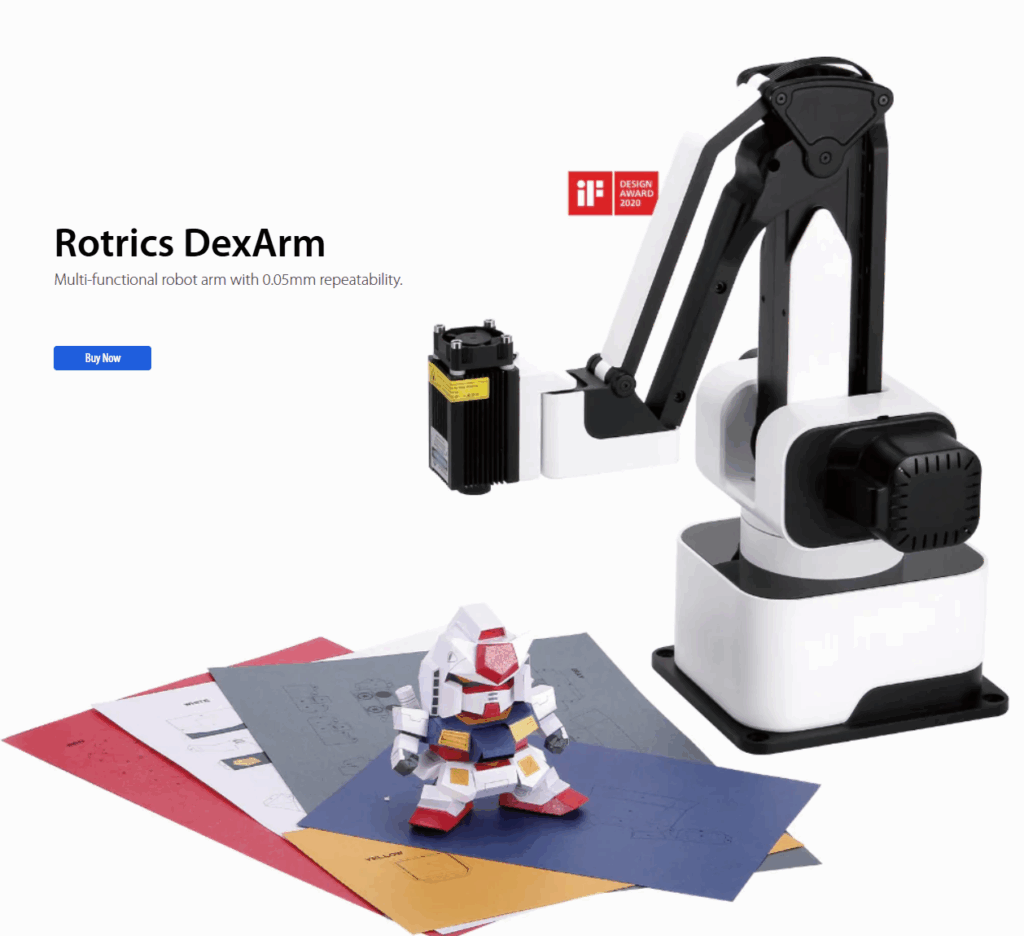
The Rotrics DexArm is a really good and cheap Chinese robot arm, which started as a Kickstarter project. I got a few of them, mostly to play around with 3D printing with multiple arms. It’s designed to do 3D printing out of the box and it’s quite good at that. It also offers rails that can allow it to move around, which are also cool. But the original promise of multiple arms being able to talk to each other and coordinate actions never really came to pass, and today although the hardware is still being sold, the software is no longer developed and the community is pretty much on its own.
Fortunately, the company sells a DIY Kit, which is supposed to allow you to add new functionality to the arm. Just what we need! Or so I thought. In truth, the DIY Kit is totally undocumented and as far as I can find, nobody has ever got it to work.
Until now! After a few days of hacking, involving scopes, logic analyzers, STM32 datasheets and digging deep in the Marlin-derivative source code to crack it
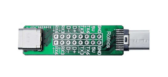
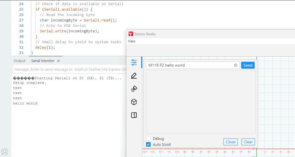
Here’s how you use it: First, the key thing to understand is that board does nothing. It’s just a USB Type C port extender. All it does is break out some of the pins of the USB port so you can get at them.
The magic is that some of the pins of the USB C port, which are typically unused, are in the case of the Rotrics arm used to send serial data from the built-in microprocessor.
So how can you use these pins? Good question! There is virtually no documentation on this, and what there is, is wrong or at least misleading (ignore all the nonsense about “PA”, “PD” or “PC” numbers that you can read here. Those are actually references to STM32F4 pins and are totally unhelpful).
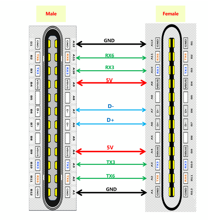
Here’s the truth. The version of Marlin Rotrics uses creates two serial ports. Serial 1 goes via the regular USB and is used to communicate with the desktop app and little TFT screen the arm comes with. Serial 2 actually goes to RX3 and TX3 as shown above. As far as I know RX6 and TX6 are not actually enabled.
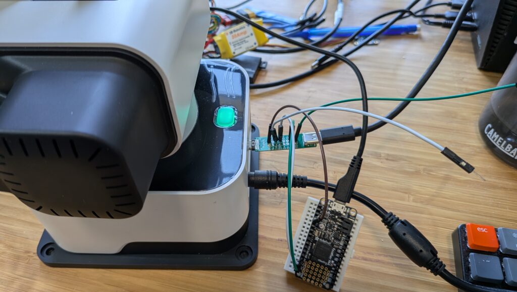
The way to get that data is to attach wires from the DIY Kit’s RX3 and TX3 pins and connect them to microprocessor like Arduino or a single-board-computer like RaspberryPi and read them as regular serial data.
Three important things to know:
The Rotrics processor is 3.3v, so you have to read the data with a 3.3v board. An old-skool Arduino (5V) will not work. I use ESP32s or, as shown above, an Adafruit Feather M4 board. Needless to say, connect the Rotrics Tx pin to your microprocessor’s Rx pin and the Rotrics Rx pin to your microprocessor’s Tx pin as usual for serial data.
Don’t forget to also connect the GND pin on that board to a Ground pin on your microprocessor.
The data comes in at a weird 1000000 baud rate.
You can send data to this serial port with the Gcode command “M118 P2 [your text]”. While you’re testing, you can send that via the Rotrics Studio terminal, as I’ve shown before, but if you’re doing 3D printing you can just embed any commands you want into your Gcode after the “M118 P2” header and program your microprocessor to read the output from that serial port and act on it in whatever way you want.
I’m going to use this to add a fourth degree of freedom (the rails) to the arms as 3D printers, so my Gcode will occasionally tell the rails to move the arms (by talking to the Arduino, which in turn talks to my laptop, which in turn talks to a stepper motor-driver board) down to the next zone of a big object.
But what’s cool about this hack is that I can now add as many other commands or functions as I want, just by embedding M118 P2 [cool command] in my Gcode whenever I want and letting code on the microprocessor or my laptop deal with the rest.
A final note: If you just want the arms to send commands or text back to your laptop via the USB cable, you don’t need this DIY kit at all! Just embed M118 P2 [cool command] in your Gcode anywhere you want and it will go back to your laptop via USB serial to be read via Python (here’s an example, which reads commands from the arms and uses it to command the rails to move to a new position via a GRBL controller). Remember that you can’t be connected to Rotrics Studio while you’re reading that serial port with Python, since Studio takes the port.
If you’re converting an off-the-shelf RC car to full autonomy with Donkeycar, one of the questions you may have is why you can’t use the RC controller the car came with instead of using a Bluetooth gaming joypad. The old answer was that the RC signal has to go through the RaspberryPi and be processed or bypassed by the Python code, depending on whether you’re in manual or autonomous mode, and there’s no good way to just insert the RaspberryPi into that process (even if you could plug your RC receiver cables into the RaspberryPi, it can’t properly handle those signals nor those necessary to drive your servo or motor controller output). Thus our old advice was to throw out your RC transmitter and receiver and use the gaming joypad instead along with an I2C servo controller board.
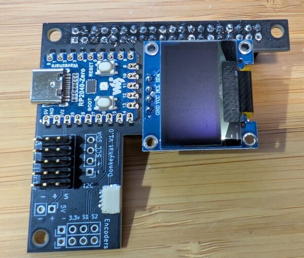
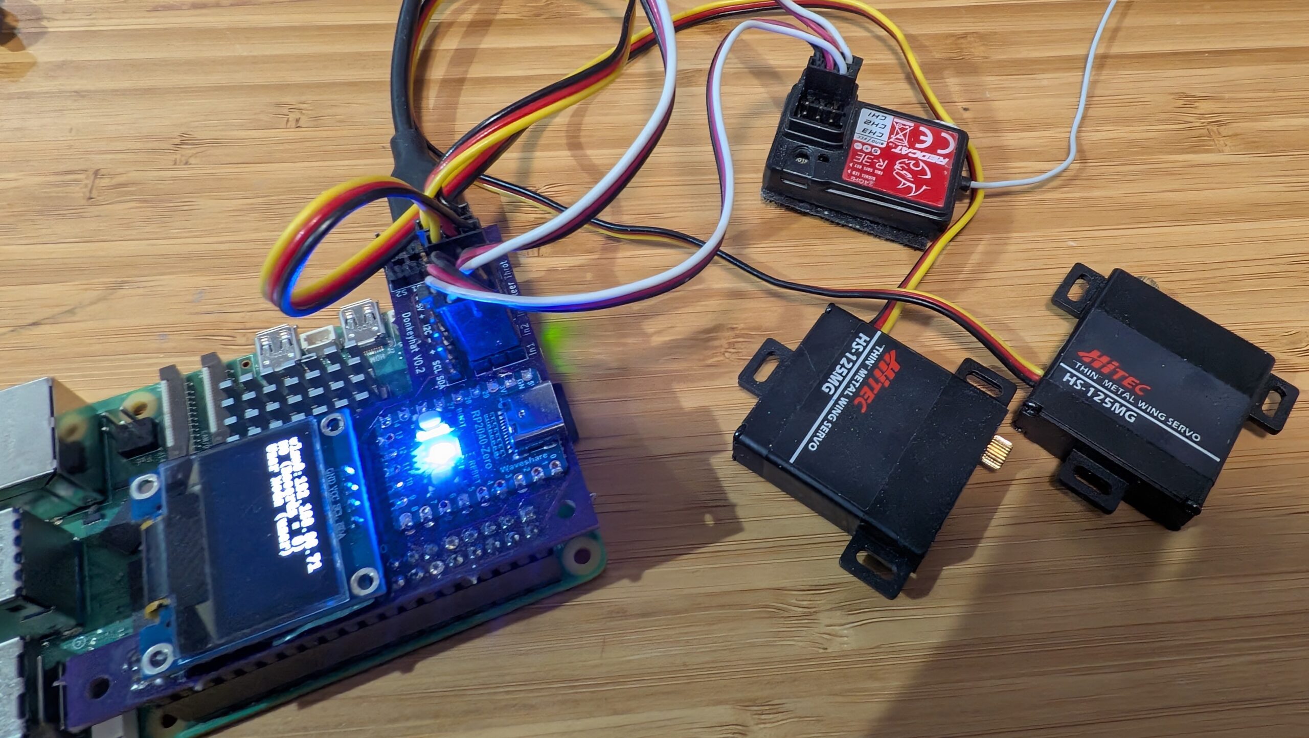
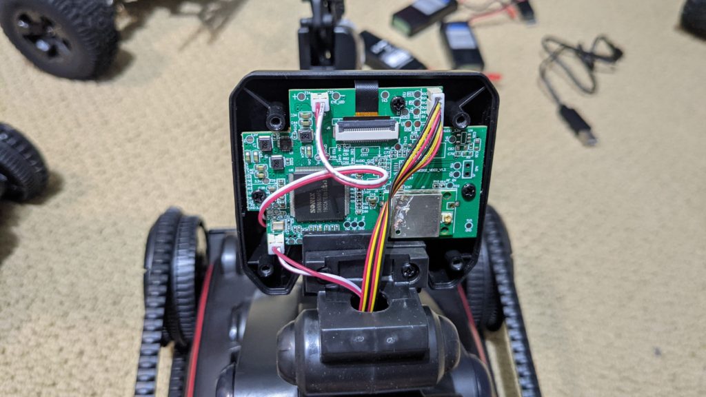
But now we have a better answer! The new RC Hat, which plugs on top of the Raspberry Pi, allows you to use your RC transmitter and receiver as is, without needing a joypad or servo driver board. Not only does that save you money, but the RC gear has way longer range, which is great for outdoors racing or racing around lots of other cars.
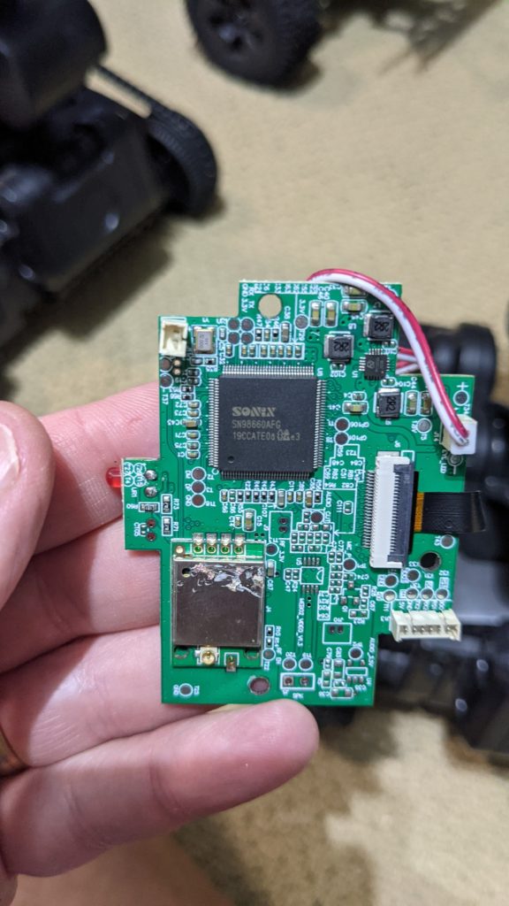
The RC hat consists of a circuit board that has a RaspberryPi 2040 Zero board on it, along with an OLED screen and the pins to plug in your RC receiver, your servos, as well as wheel encoders, other I2C devices and anything that needs 5v power. The 2040 board handles all the low-level reading of RC input and servo output and communicates with the RaspberryPi over hardware serial. The CircuitPython code for the RP2040 is here, although that’s already loaded on the board so you shouldn’t need to mess with it.
Simply use female-to-female 3-wire RC cables to connect your RC receiver into the “In 1”, “In 2” and (if you have a third channel) “In 3” pin headers. Plug your steering servo into “Steer” and your motor controller/ESC into “Throt”. Make sure you get the orientations right — black (ground) should always be on the outside next to the board edge.
To use it the hat, you’ll need to edit your myconfig.py file in your mycar directory. Make the following changes:
To enable the OLED screen, uncomment these lines and change the values as shown in the relevant areas of the myconfig.py file:
USE_SSD1306_128_32 = TrueSSD1306_RESOLUTION = 2
To enable the RC hat as output, in the “Drive train” section, uncomment and edit to this:
DRIVE_TRAIN_TYPE = "MM1"
To enable the RC hat as input, in the “Joystick” section, uncomment and edit to this:
In the “Robohat MM1 controller” section, uncomment and edit to this:
MM1_SERIAL_PORT = '/dev/ttyAMA0'
Since you probably only have 2 or 3 channels on your RC gear, all other commands and mode changes will be done via the web interface (on joypads you use dedicated buttons) via Wifi. Instructions for that are here.
The screen will come on and show the Donkey state when you start Donkey via the usual “python manage.py drive” command. It won’t be on when you’re not running Donkey, although it’s there to be used for other programs if you’d like (it’s just a standard I2C OLED screen and can be used with this Python library).
Finally, you’ll have to enable the hardware serial on the Pi. You can do this with “sudo raspi-config" Interface Options/Serial Port, which you will have already used to enable the I2C interface when setting up donkey.
If you’re using a RaspberryPi 5, that all you need to do. If you’re using a RaspberryPi 3 or 4 (or Pi Zero 2), which weirdly share the hardware serial and Bluetooth interfaces, you need to do one more thing:
You can either use “ttyS0” as the serial port in the “MM1_SERIAL_PORT” setting in your Donkeycar myconfig.py file (instead of “ttyAMA0” as described above). This should work fine, but the baud rate can vary a bit with clock speed with this approach. That hasn’t shown itself to be a problem in practice, but if you want to be safer, you can disable the Bluetooth and use the HW serial as intended at ttyAMA0:
Add this to the bottom of config.txt (enter “sudo nano /boot/firmware/config.txt"):
dtoverlay=disable-bt
Type Ctrl-O, Ctrl-X to save and exit the Nano editor
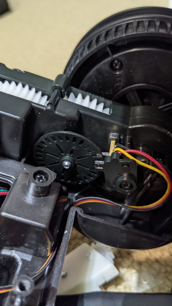
Although I’ve posted previous tutorials on adding a shaft encoder to your DIY robocar, sometimes you want the additional precision of wheel encoders. That’s because when you’re turning, the wheels move at different speeds and you can’t measure that from just the main shaft.
The problem is that it’s pretty hard to retrofit wheel encoders to these small cars; there just isn’t much room inside those wheels, especially if you’re trying to add hall-effect sensors, quadrature rotary encoders or even just the usual optical wheel with a LED/photodiode combination to read the regular cutouts as they spin.
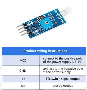
However, most wheel already have cutouts! Maybe we don’t need to use an LED at all. Perhaps a photodiode inside the wheel could look out at the lights outside the car and just count the pulses as the wheel turns, with the gaps in the wheel letting the light through.
I used these cheap photodiodes, which have both digital and analog outputs, as well as a little potentiometer to calibrate them for the available light.
Then I just connected them to an Arduino and mounted them inside the wheel, as close to the wheel as possible without binding, to avoid light leakage. The Arduino code is below. Just connect the DO pin to Arduino pin 8, and the VCC and GND pins to the Arduino’s VCC and GND pins (it will work with 3.3v or 5v). No need to connect the AO pin.
const int encoderIn = 8; // input pin for the interrupter
const int statusLED = 13; // Output pin for Status indicator
int detectState=0; // Variable for reading the encoder status
int prevState = 1;
int counter = 0;
void setup()
{
   Serial.begin(115200);
   pinMode(encoderIn, INPUT); //Set pin 2 as input
   pinMode(statusLED, OUTPUT); //Set pin 13 as output
}
void loop() {
   detectState=digitalRead(encoderIn);
   if (detectState == HIGH) {
    detectState=digitalRead(encoderIn);  // read it again to be sure (debounce)
    if (detectState == HIGH) {
      if (prevState == 0) { //state has changed
      digitalWrite(statusLED, HIGH); //Turn on the status LED
      counter++;
      Serial.println(counter);
      prevState = 1;}
      }
   }
   if (detectState == LOW && prevState == 1) { //If encoder output is low
      digitalWrite(statusLED, LOW); //Turn off the status LED
      prevState = 0;
   }
  }
When you run a Raspberry Pi in “headless” configuration without a screen, which is typical for a Donkeycar setup, one of the tricky things is knowing what IP address it has been assigned by your Wifi network, so you can connect to it. If you control your own network, you may be able to see it in your network control app, shown in a list of connected devices. But if you don’t control your own network, such as the races we run at Circuit Launch, it’s hard to figure out which Raspberry Pi on the network is yours.
So what you need is a screen that shows you your IP address on startup. This is harder than it should be, in part because of changing startup behavior in various different kinds of Linux and generations of Raspian, and I wrote a post last year on how to do it with a simple LED screen.
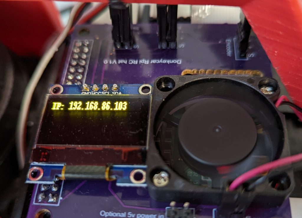
Now we’re standardizing on smaller, more modern color OLED screens. So this is an update to show how to use them to show your IP address on startup.
Update: All too typically, after I write this code myself I find that there’s a perfectly good repo already out there that does the same thing by slightly different means. So check that one out and use whichever you prefer.
Note: In the picture above, I’m using the custom Donkeycar RC hat (coming soon to the Donkey Store), which has a built-in OLED screen. But if you don’t have that, you can connect your OLED screen directly with jumper cables as per this tutorial.
Step 1: Install Adafruit’s Circuit Python OLED library. If your Pi boots into a Conda environment, exit that (conda deactivate), then install the library with pip: pip install adafruit-circuitpython-ssd1306
Step 2: Copy this Python file to your top level user directory (probably /home/pi/)
Step 3: Set it to run at startup. Type crontab -e and then select the editor you prefer (I use Nano). Then add @reboot python3 /home/pi/oled_ip.py to the bottom of the file. Then save it and exit the editor (control-o, control-x).
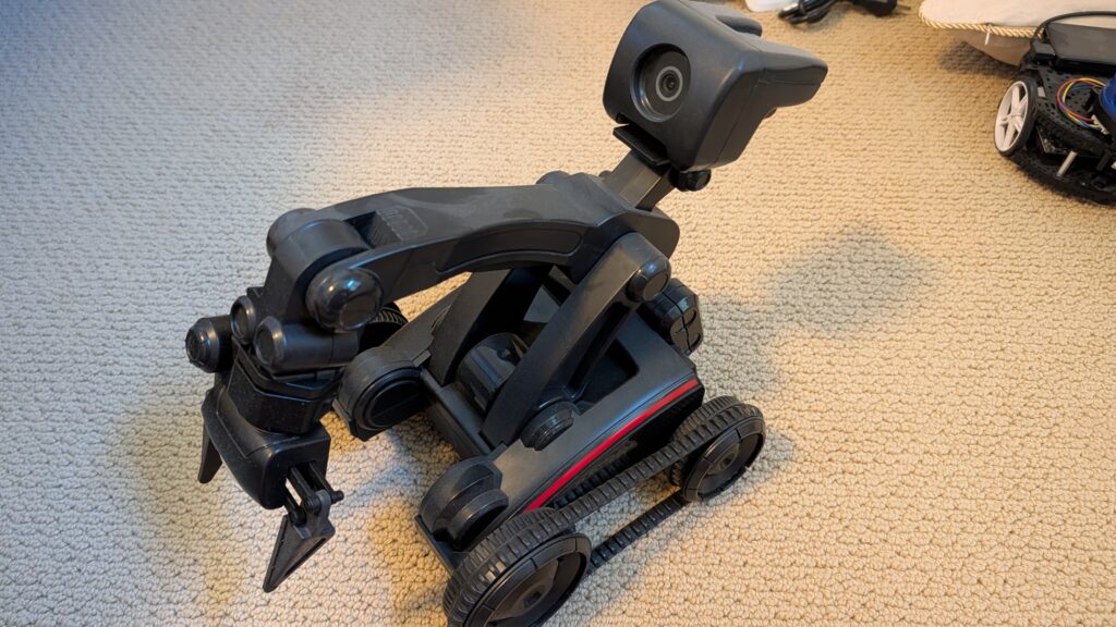
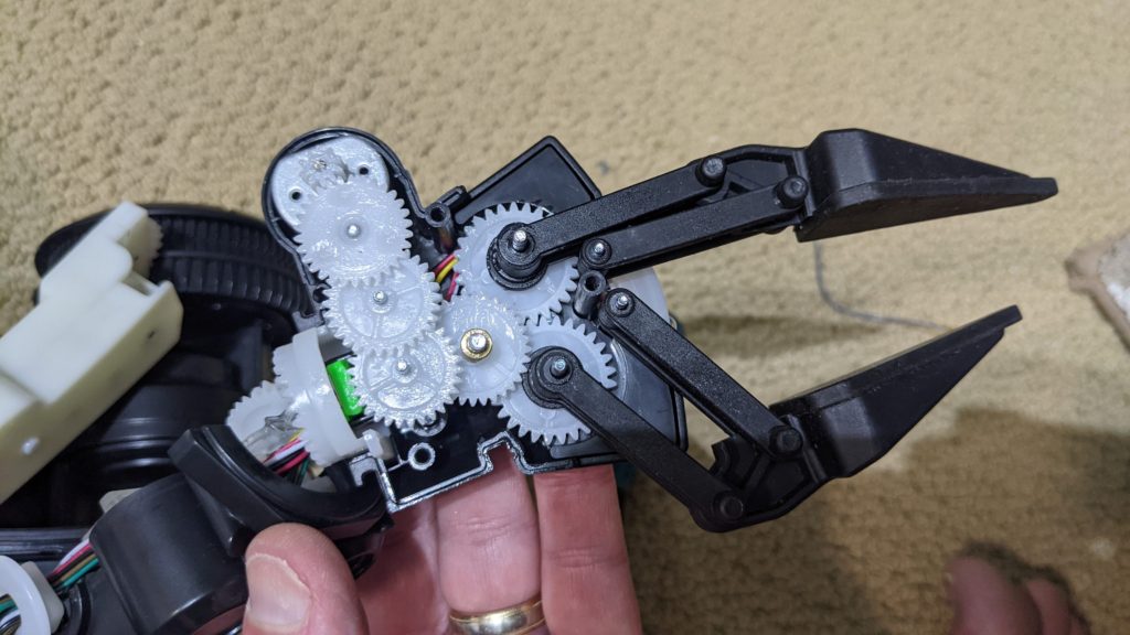
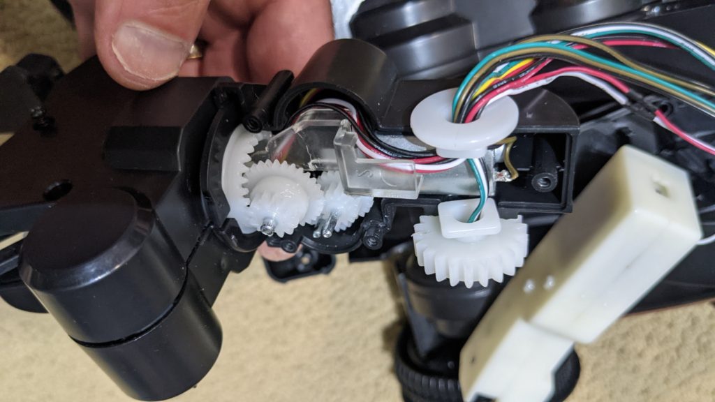
I backed the Naobot AI robot on Kickstarter, and actually got two of them (the first was defective, so they sent me another). So I took apart the defective one to see how it works inside. Overall, it looks very well done.
Right now it’s mostly useful as a programming platform, using Scratch in its mobile app. The built-in “AI” functions, such as follow a person or animal, don’t work very well. But on the hardware side, it’s quite impressive.
Here’s what’s inside:
All the “brains” are in the board in the head that includes the camera, the processor and the wifi board
Here’s a close-up of that boardInside the arm are motor gearboxes for each jointEach gearbox has the usual motor, gears and a potentiometer or encoder to measure positionHere’s a close-up of the wheel encodersThe motor train is well-designed and has wheel encoders on both tracksHere’s the gear train for the “fingers”This one rotates the “wrist”An close-up of the potentiometers that close the loop for motor movementThis is the “elbow” joint
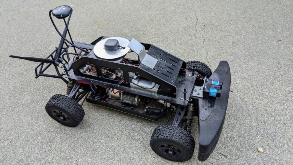
Back in the days of the much-missed Sparkfun Autonomous Vehicle Competition (2009-2018), I and other team members did very well with GPS-guided rovers based on the ArduRover software, which was a spin-off from our drone work. Although we won a lot, there was a lot of luck and randomness to it, too, mostly because GPS was not very precise and positions would drift over the course of the day.
Now that GPS and other other sensors used by ArduPilot have improved, as has the codebase itself, I thought I’d come back to it and see how much better I could get a rover to perform with all the latest, greatest stuff.
The answer is: better! Here’s a how-to.
For this experiment, I used a rover with a Pixhawk 4 autopilot, a Reach RTK M+ rover GPS (on the car) and RS+ base station. This is pretty expensive gear (more than $1,000 for the RTK combo alone) so I don’t expect others to be able to duplicate this (I borrowed the gear from work). However, you don’t actually need the expensive base station — you can use the $265 M+ rover GPS by itself, using Internet-based corrections instead of a local base. There are also cheaper solutions, such as the $600 Here+ base/rover combo or just a $125 Here 3 using Internet-based corrections.
The promise of RTK GPS is that by using a pair of high-quality GPSs, one stationary in a known spot and the other moving on the car, you can detect the atmospheric disturbances that lead to GPS drift on the stationary one (since any apparent movement is clearly noise) and then transmit the necessary corrections to the nearby moving GPS, so it can correct itself. The closer the stationary GPS is to the moving one, the more accurate the RTK solution. So my base station right on the track was perfect, but if you use Internet correction sources and are either near the coasts or farming country (farms use RTK GPS for automated agricultural equipment), you should be able to find a correction source within about 10-20km.
If this works, it should avoid the biggest problem with just using the GPS on the car, which is drift. We often found at the Sparkfun AVC that a waypoint mission around the course that worked great in the morning was several meters off in the afternoon because it was using different GPS satellites. So repeatability was a real issue.
My rover is a standard 1/10th scale RC chassis with a brushed motor and a big-ass foam bumper on the front (trust me, you’ll need a bumper). It honestly doesn’t matter which one you use; even 1/16th can work. Don’t bother to get one with a RC radio, since you’ll want more channels than a standard car radio provides (you use the extra channels to do things like switch modes and record waypoints). Something like this, with this radio (you’ll need CPPM output on the RC receiver), would be fine. I tend to use 2S (7.4v) LiPo batteries so the car doesn’t go too fast (that’s the same reason for using a brushed rather than brushless motor, although either can work). Just make sure that it’s got a proper separate steering servo and ESC; none of those cheap toy integrated deals.
A couple things I added that are useful:
It’s hard to get the standard 3DR telemetry radios to work well at ground level. So I use the long-range RF900D+ radios instead. Those are pretty expensive, so you will probably want to use the cheaper and still very good 500mw Holybro radios (which are designed to work with the Pixhawk 4) instead.
I cut out an aluminum circle to put under the Reach RTK GPS receiver, which was recommended. You can also buy those pre-made from Sparkfun.
You’ll notice a two-barrel sensor at the front of the car. That’s a Lidar-Lite range sensor, which I’ll eventually use for obstacle avoidance
The first task was to set it up, which was not easy.
Setting up the RTK
First, you have to set up the RTK pair. In the case of the Reach RTK, both base and rover (which is the name for the GPS module that moves) can connect via wifi, either to an existing network or to one that they set up themselves. You can either use a web browser or a mobile app to set them up, update the firmware if necessary and monitor their performance. A few things to keep in mind, along with following the instructions:
You do have to tell the base where it is (enter lat/lon), or set it to sample its own position for 2 minutes (use Single mode, since it isn’t getting corrections from anywhere else). I usual use the sampling method, since Google maps on my phone is not as accurate.
On the rover, select “Kinematic mode” and tell it to accept horizontal motion of 5 m/s
On the rover, set it to stream its position over Serial using NMEA format at 38kbs.
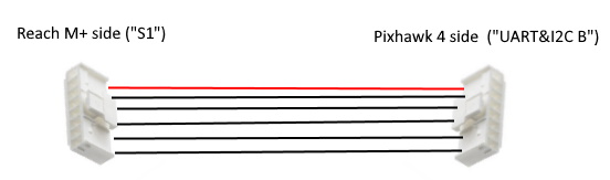
If you’re using a Pixhawk 4 like me (and perhaps other Pixhawk-based autopilots), you’ll have to make a custom cable, since for some dumb reason Reach and Pixhawk use Serial connector pinouts that are mirrored. On Pixhawk, V+ is the red wire on the left of the connector, while on the M+ it’s on the right. Super annoying. Basically just take a spare six-pin cable for the Reach and a spare for the Pixhawk (they’re mirrored), cut them and resolder the wires (use heat shrink tubing on each) in the same order counting from the red wire. Like this:
Setting up ArduRover
In my setup, I’m using both the standard GPS that comes with the Pixhawk 4 as well as the Reach RTK GPS.
So we’ll start by setting up ArduRover so it works with the standard Pixhawk GPS, and then we’ll add the second RTK GPS. There are a couple tricks to setting up ArduRover, which you should keep in mind in addition to the instructions:
After you do the regular setup, there are a lot of tuning instructions. This can be a bit overwhelming, but these are the ones that are most important:
First, your steering may be reversed. There are actually two steering modes: manual and auto. First, start with auto mode. Create a mission in Mission Planner, arm and put your rover in auto mode. If it steers towards the first waypoint, great; if it steers away, that means that your output is reversed and change the Servo 1 parameter to Reversed. Once you’ve got that sorted, do the same thing for Manual Mode: if moving your right stick to the right makes the car steer to the right, great; if not, change the RC1 parameter to Reversed.
Once you’ve got that right, you can focus on getting the rover to track the course as well as possible. There is a page on doing this, but three parameters that are good to start with are these:
Steering P (proportional) value. The default is pretty low. Try raising it to 0.8 or 0.9. If your rover zig-zags fast when it’s supposed to be going straight, you’ve gone too far. Dial it back a bit
Tune the L1 controller. I find that it’s too conservative out of the box. I use a NAVL1_PERIOD of 6 (vs default 10) and a NAVL1_DAMPING of .90 (vs default 0.75) on my rover.
Adding the second RTK GPS
Once your rover is running well with the built-in GPS, you can add the second RTK one. Once you plug it into the second UART port, you can enable it by setting the following parameters:
GPS2_TYPE2 to 5 (auto)
GPS_BLEND_MASK to 1 (just horizontal)
GPS_BLEND_TC to 5.0s (quick averaging)
GPS_AUTO_SWITCH to 2 (blend)
SERIAL4_BAUD to 38 (38,400 bps)
SERIAL4_PROTOCAL to 5 (GPS)
Once you’ve set all those, reboot your autopilot. If you’re outside, when you restart and give the GPSs time to settle, you should see both listed on the Mission Planner HUD. (Note: it’s important to do all this testing outside. If your RTK can’t see satellites, it won’t stream a solution and you won’t see a second GPS in the Mission Planner.)
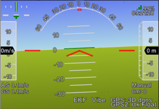
When it’s working, you should see this: two GPSs shown in the HUD (it will say “Fixed” or “Float” depending on how good your RTK solution is at any given moment):
We’re going to “blend” the RTK and the regular GPS. Why not just use RTK, which should be more accurate? Because sometimes it totally glitches out and shows a position many meters away, especially when you go under trees. So we use the less accurate but more reliable regular GPS to “smooth out” the GPS, which dampens the glitches while still allowing the higher precision (usually) RTK to dominate. The above parameters work pretty well for me.
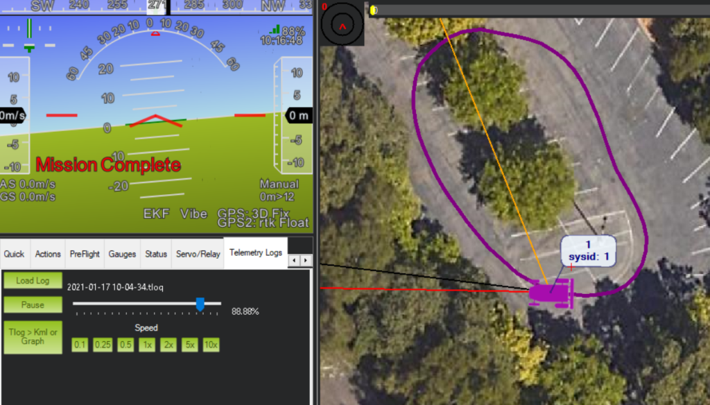
Here’s a replay of the log of one run at 5m/s, which is pretty much perfect. If you want to go even faster, you’ll need to tune it a bit more, but this is quite promising.
So, the final question is: is RTK worth it? I think, on balance, the answer is no. New regular GNSS GPSs using the Ublox M8 and M9 chip sets (I like the MRo range) are getting much better and there are more satellite constellations for them to see. $1,000 and a harder setup is a lot of money and hassle for slightly better performance. So what’s RTK good for? Mostly for industrial rovers that need to be in an exact position, such a agricultural and construction machinery. For DIY Robocar racing, I think you’d be better off with regular GPS.