(This has nothing to do with robocars but I had to post it somewhere)
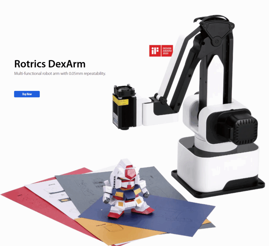
The Rotrics DexArm is a really good and cheap Chinese robot arm, which started as a Kickstarter project. I got a few of them, mostly to play around with 3D printing with multiple arms. It’s designed to do 3D printing out of the box and it’s quite good at that. It also offers rails that can allow it to move around, which are also cool. But the original promise of multiple arms being able to talk to each other and coordinate actions never really came to pass, and today although the hardware is still being sold, the software is no longer developed and the community is pretty much on its own.
Fortunately, the company sells a DIY Kit, which is supposed to allow you to add new functionality to the arm. Just what we need! Or so I thought. In truth, the DIY Kit is totally undocumented and as far as I can find, nobody has ever got it to work.
Until now! After a few days of hacking, involving scopes, logic analyzers, STM32 datasheets and digging deep in the Marlin-derivative source code to crack it
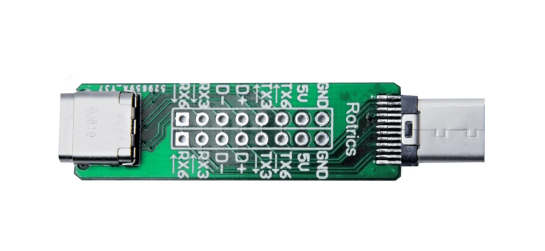
Here’s how you use it: First, the key thing to understand is that board does nothing. It’s just a USB Type C port extender. All it does is break out some of the pins of the USB port so you can get at them.
The magic is that some of the pins of the USB C port, which are typically unused, are in the case of the Rotrics arm used to send serial data from the built-in microprocessor.
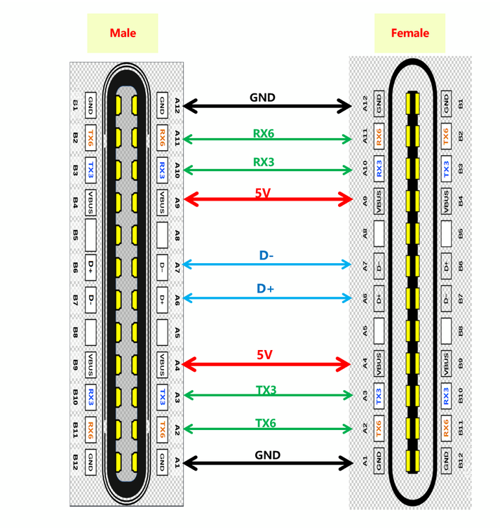
So how can you use these pins? Good question! There is virtually no documentation on this, and what there is, is wrong or at least misleading (ignore all the nonsense about “PA”, “PD” or “PC” numbers that you can read here. Those are actually references to STM32F4 pins and are totally unhelpful).
Here’s the truth. The version of Marlin Rotrics uses creates two serial ports. Serial 1 goes via the regular USB and is used to communicate with the desktop app and little TFT screen the arm comes with. Serial 2 actually goes to RX3 and TX3 as shown above. As far as I know RX6 and TX6 are not actually enabled.
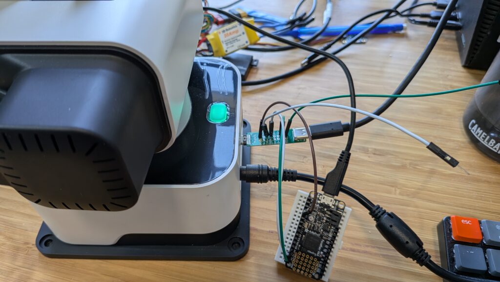
The way to get that data is to attach wires from the DIY Kit’s RX3 and TX3 pins and connect them to microprocessor like Arduino or a single-board-computer like RaspberryPi and read them as regular serial data.
Three important things to know:
- The Rotrics processor is 3.3v, so you have to read the data with a 3.3v board. An old-skool Arduino (5V) will not work. I use ESP32s or, as shown above, an Adafruit Feather M4 board. Needless to say, connect the Rotrics Tx pin to your microprocessor’s Rx pin and the Rotrics Rx pin to your microprocessor’s Tx pin as usual for serial data.
- Don’t forget to also connect the GND pin on that board to a Ground pin on your microprocessor.
- The data comes in at a weird 1000000 baud rate.
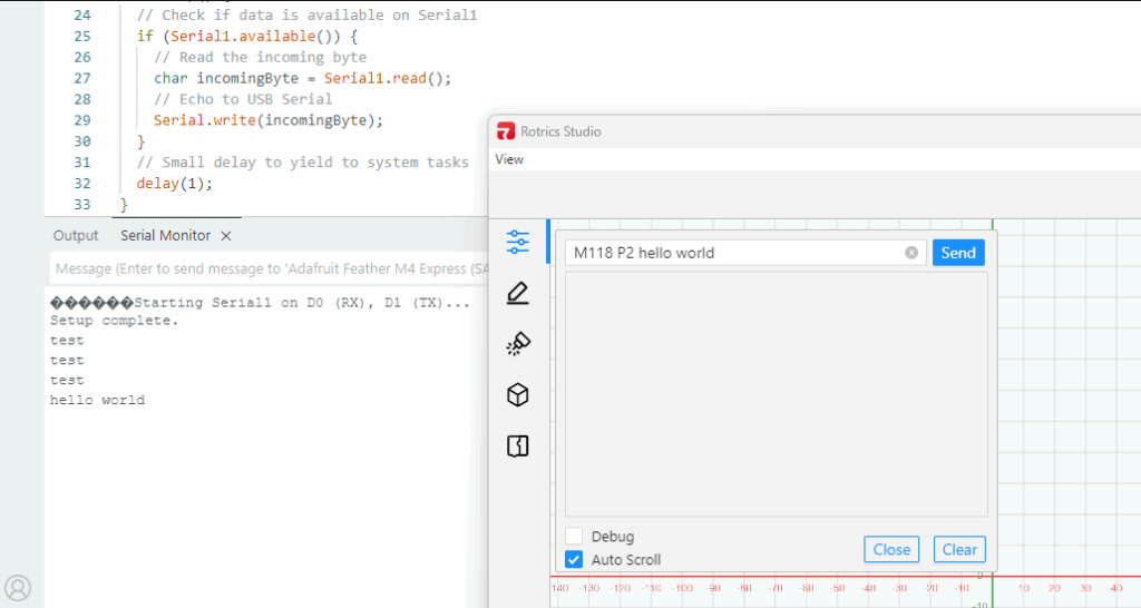
- You can send data to this serial port with the Gcode command “M118 P2 [your text]”. While you’re testing, you can send that via the Rotrics Studio terminal, as I’ve shown before, but if you’re doing 3D printing you can just embed any commands you want into your Gcode after the “M118 P2” header and program your microprocessor to read the output from that serial port and act on it in whatever way you want.
I’m going to use this to add a fourth degree of freedom (the rails) to the arms as 3D printers, so my Gcode will occasionally tell the rails to move the arms (by talking to the Arduino, which in turn talks to my laptop, which in turn talks to a stepper motor-driver board) down to the next zone of a big object.
But what’s cool about this hack is that I can now add as many other commands or functions as I want, just by embedding M118 P2 [cool command] in my Gcode whenever I want and letting code on the microprocessor or my laptop deal with the rest.
A final note: If you just want the arms to send commands or text back to your laptop via the USB cable, you don’t need this DIY kit at all! Just embed M118 P2 [cool command] in your Gcode anywhere you want and it will go back to your laptop via USB serial to be read via Python (here’s an example, which reads commands from the arms and uses it to command the rails to move to a new position via a GRBL controller). Remember that you can’t be connected to Rotrics Studio while you’re reading that serial port with Python, since Studio takes the port.
3D print with the rail?? Wow! Please please post a video ( and publish your code? 😀 ) when you manage to print something. cheers
Here’s an example with code
https://github.com/zlite/railprinter/
I will attempt this, thanks!