Evaluating the Quectel LG290P GNSS RTK Receiver and the Micoair LR900-F LoRa

I was recently given a Quectel LG290P GNSS RTK Receiver and a Micoair LR900-F LoRa to evaluate for use as a Rover in combination with an appropriate Base Station for outdoor autonomous RC car racing.
The Quectel LG290P GNSS RTK Receiver came in the form of a Sparkfun Quadband GNSS RTK Breakout Board and the Micoair LR900-F LoRa came as a two Telemetry Radio set.

The Hardware. The Quectel LG290P GNSS RTK module is a quad-band, multi-constellation, high-precision, RTK GNSS receiver. The module is capable of simultaneously receiving signals from the L1L2L5, and L6/E6 bands. The module has a built-in NIC anti-jamming unit which provides professional-grade interference signal detection and elimination algorithms effectively mitigating multiple narrow-band interference sources and significantly improving signal reception performance in complex electromagnetic environments. Additionally, the embedded algorithms ensure reliable positioning in complex scenarios such as urban environments and deep tree cover.

The LR900-F Telemetry Radio is a small, inexpensive radio with superior performance as a long range Telemetry Radio for the transmission of RTCM3 correction messages between the Rover and the Base Station. The LR900-F transmits in the 915MHz (890-915MHz) range, has an adjustable RF power output of up to 500mW, and uses LoRa modulation technology and frequency hopping spread spectrum to obtain excellent anti-interference performance. Additionally the LR900-F uses transparent transmission to to provide compatibility with any data and protocol.

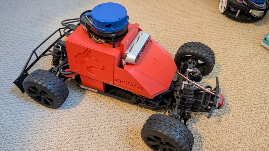
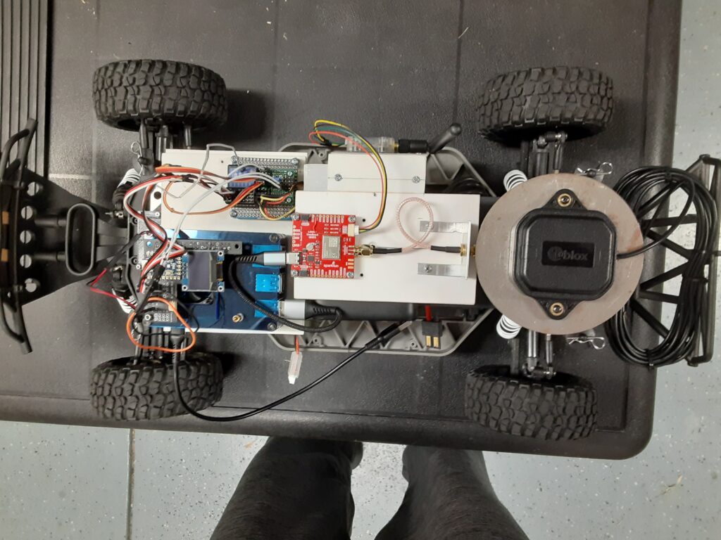
The RC Car Rover Test Vehicle is a Traxxas 1/10 scale Slash Truck chassis that started life as a 2WD BL-2 and was converted to 4WD with a brushless motor/ESC and a 4X4 conversion kit powered by a single 2S 5200mah LiPo battery. The Test Vehicle, for the purpose of this evaluation, also includes a Raspberry Pi 4B+ 4GB SBC, a Donkey Car RC HAT, a u-blox GNSS All-Band High Precision Antenna, a Fly Sky RC Receiver, and an Anker Power Core 13000 Lion battery.

The Preparation. Prior to mounting the Sparkfun Quadband GNSS RTK Breakout Board and the Micoair LR900-F Telemetry Radio on the Slash chassis, I modified the configuration of the LG290P Receiver using the Quectel QGNSS app as follows:
1) Configured UART1 for 115200 baud.
2) Configured UART3 for 57600 baud.
3) Configured the UART1 USB output for only four pertinent NMEA messages.
And modified the Micoair LR900-F LoRa using the Micoair Micoassistant app as follows:
1) Configured the Broadcast Mode for Rx only.
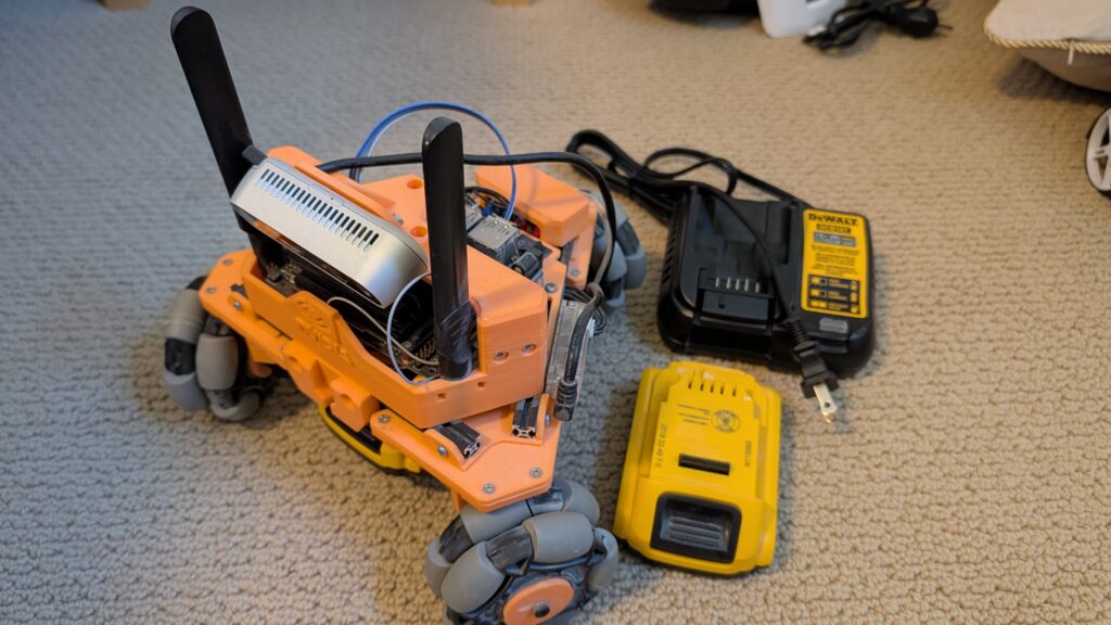
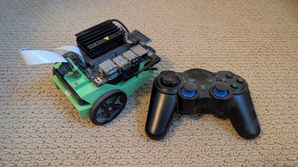
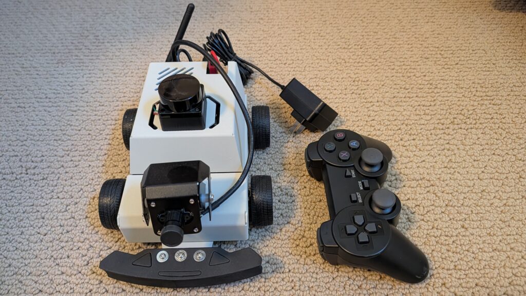
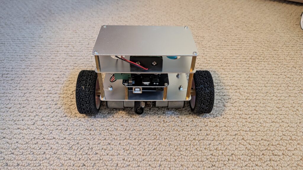
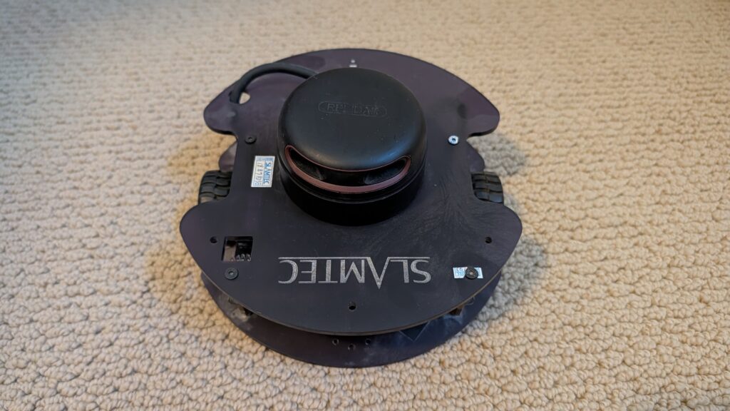
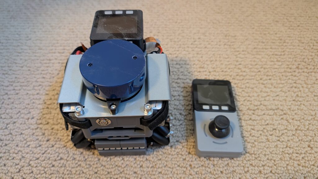
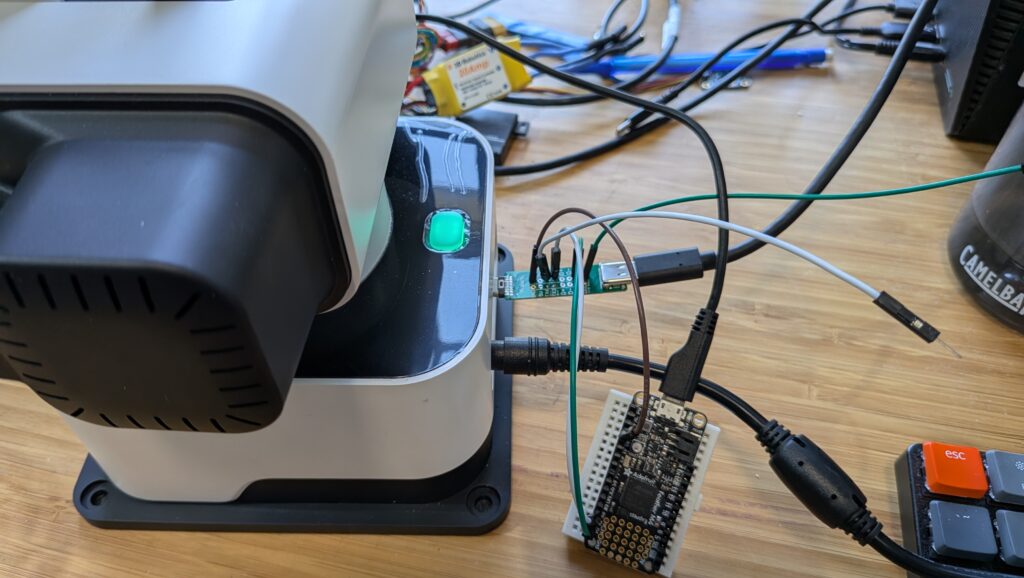
I then mounted the Sparkfun Quadband GNSS RTK Breakout Board and the Micoair LR900-F Telemetry Radio on a sub chassis along with the Raspberry Pi 4B+/RC HAT, the u-blox precision antenna, the RC Receiver and the Anker Power Core 13000 Lion battery as shown in the photos below.

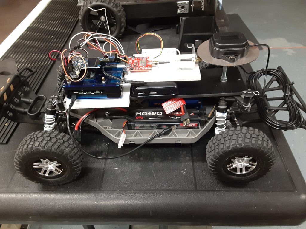
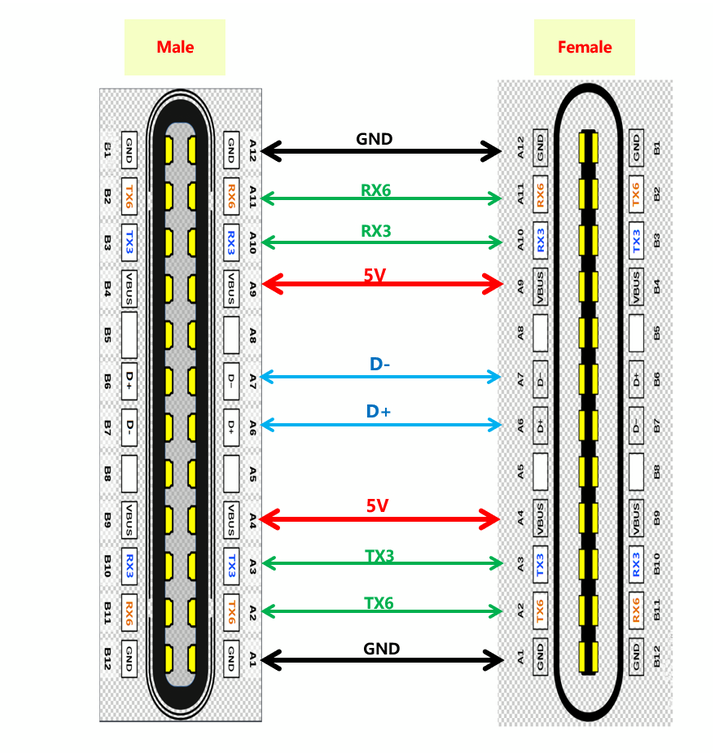
The LR900-F Telemetry Radio is connected over a four wire cable to the UART3 port on the Breakout Board while the u-blox precision antenna is connected to the SMA connector on the Breakout Board. The Sparkfun Quad band GNSS RTK Breakout Board interfaces with the Raspberry 4B+ over a USB connection.

The Evaluation. To begin the evaluation, I setup and powered up my trusty Sparkfun RTK Postcard/Portability Shield Base Station, which includes a Micoair LR900-F Telemetry Radio, in the Broadcast Tx mode for transmission of RTCM3 correction messages to the Rover, in my home’s driveway with a clear view of the sky as my autonomous vehicle test course is the neighborhood street in front of my house. I powered up the Raspberry Pi 4B+ on the Slash Rover along with the ESC and used my HP laptop to SSH into the CLI, running on the Rover’s Raspberry Pi 4B+, and changed to the mycar directory. Then I drove the Rover out into the street in front of my driveway, aligned it with a chalk line starting point as a reference, and verified that the RTK LED on the Receiver Breakout Board was a solid white indicating a RTK Fix solution.
Returning to my laptop I started the path_follow.py program with python manage.py drive on the CLI, opened the Donkey Car webui using Google on the laptop, reset the car origin, hit the start recording button and used the RC transmitter to slowly drive the Rover around my neighborhood street test course collecting GPS latitude and longitude coordinates every 0.2 meters until the Rover arrived back at the chalk line origin starting point. At which time I stopped the course recording and saved the recorded course as donkey_path.csv for course playback.

The Results. Now comes the real test which is to see how well the Rover can autonomously drive the previously recorded course with P and D values based on my previous autonomous Rover experience. Using the Donkey Car webui I reset the Rover’s origin position at the starting line, selected “Full Auto”, and proceeded to watch the Rover move off of the starting line at a moderate speed, as I am using a preset PID speed value, and head straight North up the neighborhood street and make a perfect 180 degree left U turn to the other side of the street. The Rover then headed South back down the street for the next 180 degree left hand U turn at the other end of the Indy style raceway course. After completing the 180 degree left hand U turn at the end of the course, the Rover then continued North on a reasonably perfect beeline path to the start of the course so I let it continue for ten more laps without any issues like going off course and crashing into the curb.

The Conclusions. Compared to my ZED-F9P RTK GNSS Receiver equipped Traxxas E-Maxx Rover, the LG290P RTK GNSS Receiver equipped Traxxas Slash Rover appeared to negotiate the 180 degree left hand U turns with little or no overshoot compared to the E-Maxx Rover and exhibited much less straightaway course hunting than the E-Maxx Rover. However it will be interesting to see how well the E-Maxx Rover performs when equipped with a LG290P RTK GNSS Receiver which will be the subject of my next blog post.
As for the performance of the Micoair LR900-F LoRa Telemetry Radios, I can definitely recommend them as I was able to drive the Slash Rover over a quarter of a mile LOS from the Base Station, with the Base Station Micoair Telemetry Radio set at MIN power output, and not lose the Base Station Telemetry Signal. Since I was running the Base Station Micoair Telemetry Radio at MIN power output, I would say that there is plenty of output power margin for farther LOS distances or challenging urban environments when running the Telemetry Radio at the MID or MAX power output settings.


Giving away lots of cool robocars [Update: all taken!]

I’m clearing out my workshop and giving away a bunch of wheeled robots, all in good condition, that I won’t have time to use. These are free to a good home, but you must be willing to pick them up in the San Francisco Bay Area, either in East Bay or Palo Alto. DM me on Twitter/X or LinkedIn if you’d like something, and I’ll update the post as they go to show what’s still available.

Sadly, this is only about 30% of my collection. I may have a bit of a robot car addiction.

[now taken]

This is Musher.io, a very nice robot car with all the fixin’s from the University of Washington. It’s $1,000 worth of gear, from the Jetson Nano to the lidar, depth camera, VESC motor controller and fast and robust RC car chassis. ROS-based.


[now taken]

Yujin Kobuki robot platform. Like a Roomba Create, but optimized for robotics and adding sensors and actuators. Comes with recharging dock. $800 value.


[now taken]

Amazon DeepRacer with stereo cameras and lidar. Was $800 new, including add-ons. Fully loaded!


[now taken]

RAE robot from OpenCV with OAK depth camera. Still in the box.


Moorebot Scout.


[now taken]

Nabot AI. Programmable tank-tread bot with arm and grasper


[now taken]

Nvidia Isaac Kaya robot. Gift from the Nvidia team. Includes Jetson with depth camera and closed-loop Dynamixel drives.


Ximpatico Scout “AI coding smart robot” with camera and app programming


Parrot Jumping Sumo wheeled drone


[now taken]

Nvidia Jetbot. Also a gift from the Nvidia team.


[now taken]

Yahboom RaspberryPi 5 ROS2 car, 4WD with encoders. Lidar, camera


[now taken]

Tinkergen MARK. Very nice robot kit, with all accessories and box. Easy to program and learn AI with.


[now taken]

Ready to run balance-bot with encoded and geared wheel motors. Super solid. Arduino-based.


[now taken]

Slamtech SDP mini robot platform. With Lidar. Does SLAM out of the box


[now taken]
M5Stack Lidar Car lidar car with mecanum wheels and controller


[now taken]
Zumi robot car. RaspberryPi-based. Can drive along a track and even obey stop signs and signals. Adorable!


[now taken]
Microsoft Project Moab balancing platform. “Teach an AI brain to balance a ball in the center of a plate using a custom simulator and sample code.” Prototype, never released! Works

Tips for installing Donkeycar on the Waveshare PiRacer Pro

The $268 Waveshare PiRacer Pro (Waveshare, Amazon) is my favorite ready-to-run Donkeycar autonomous car, at least as far as the hardware goes. But it comes with badly outdated software, which is no longer supported by the Donkeycar project. So when you get one, the first thing you’re going to want to do is load the latest Donkeycar, which works great on that hardware.

Here are some tips on doing that.

First, install the latest RaspberryPi OS on the SD card, following these instructions.

Once you’ve done that, SSH into the Pi and after you’ve updated the OS (“sudo apt update", “sudo apt upgrade"), make sure you enable I2C using "sudo raspi-config").

Then you can you create the Donkeycar app by following these instructions.

Before you can run Donkeycar, you need to customize some settings in the myconfig.py file in your mycar directory.

Enable the OLED screen by uncommenting this line and setting it to True (note that the OLED will only show text when you’re running Donkeycar, which you’ll do later when you’re ready to drive with “python manage.py drive“).

Enable the game controller that comes with the car by uncommenting and setting the Use Joystick as Default to True if is not already.

It will default to Xbox mode. To ensure that your gamepad is in Xbox mode, hold the Home button for 7 seconds after powering it on

That’s it! Your Waveshare car should be ready to train and race like any other Donkeycar. Return to the docs to learn how to do that.

Rotrics DexArm DIY Kit: The Missing Manual

(This has nothing to do with robocars but I had to post it somewhere)

The Rotrics DexArm is a really good and cheap Chinese robot arm, which started as a Kickstarter project. I got a few of them, mostly to play around with 3D printing with multiple arms. It’s designed to do 3D printing out of the box and it’s quite good at that. It also offers rails that can allow it to move around, which are also cool. But the original promise of multiple arms being able to talk to each other and coordinate actions never really came to pass, and today although the hardware is still being sold, the software is no longer developed and the community is pretty much on its own.

Fortunately, the company sells a DIY Kit, which is supposed to allow you to add new functionality to the arm. Just what we need! Or so I thought. In truth, the DIY Kit is totally undocumented and as far as I can find, nobody has ever got it to work.

Until now! After a few days of hacking, involving scopes, logic analyzers, STM32 datasheets and digging deep in the Marlin-derivative source code to crack it

Here’s how you use it: First, the key thing to understand is that board does nothing. It’s just a USB Type C port extender. All it does is break out some of the pins of the USB port so you can get at them.

The magic is that some of the pins of the USB C port, which are typically unused, are in the case of the Rotrics arm used to send serial data from the built-in microprocessor.

So how can you use these pins? Good question! There is virtually no documentation on this, and what there is, is wrong or at least misleading (ignore all the nonsense about “PA”, “PD” or “PC” numbers that you can read here. Those are actually references to STM32F4 pins and are totally unhelpful).

Here’s the truth. The version of Marlin Rotrics uses creates two serial ports. Serial 1 goes via the regular USB and is used to communicate with the desktop app and little TFT screen the arm comes with. Serial 2 actually goes to RX3 and TX3 as shown above. As far as I know RX6 and TX6 are not actually enabled.

The way to get that data is to attach wires from the DIY Kit’s RX3 and TX3 pins and connect them to microprocessor like Arduino or a single-board-computer like RaspberryPi and read them as regular serial data.

Three important things to know:

  1. The Rotrics processor is 3.3v, so you have to read the data with a 3.3v board. An old-skool Arduino (5V) will not work. I use ESP32s or, as shown above, an Adafruit Feather M4 board. Needless to say, connect the Rotrics Tx pin to your microprocessor’s Rx pin and the Rotrics Rx pin to your microprocessor’s Tx pin as usual for serial data.
  2. Don’t forget to also connect the GND pin on that board to a Ground pin on your microprocessor.
  3. The data comes in at a weird 1000000 baud rate.
  4. You can send data to this serial port with the Gcode command “M118 P2 [your text]”. While you’re testing, you can send that via the Rotrics Studio terminal, as I’ve shown before, but if you’re doing 3D printing you can just embed any commands you want into your Gcode after the “M118 P2” header and program your microprocessor to read the output from that serial port and act on it in whatever way you want.

I’m going to use this to add a fourth degree of freedom (the rails) to the arms as 3D printers, so my Gcode will occasionally tell the rails to move the arms (by talking to the Arduino, which in turn talks to my laptop, which in turn talks to a stepper motor-driver board) down to the next zone of a big object.

But what’s cool about this hack is that I can now add as many other commands or functions as I want, just by embedding M118 P2 [cool command] in my Gcode whenever I want and letting code on the microprocessor or my laptop deal with the rest.

A final note: If you just want the arms to send commands or text back to your laptop via the USB cable, you don’t need this DIY kit at all! Just embed M118 P2 [cool command] in your Gcode anywhere you want and it will go back to your laptop via USB serial to be read via Python (here’s an example, which reads commands from the arms and uses it to command the rails to move to a new position via a GRBL controller). Remember that you can’t be connected to Rotrics Studio while you’re reading that serial port with Python, since Studio takes the port.